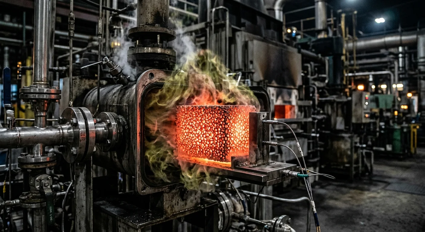
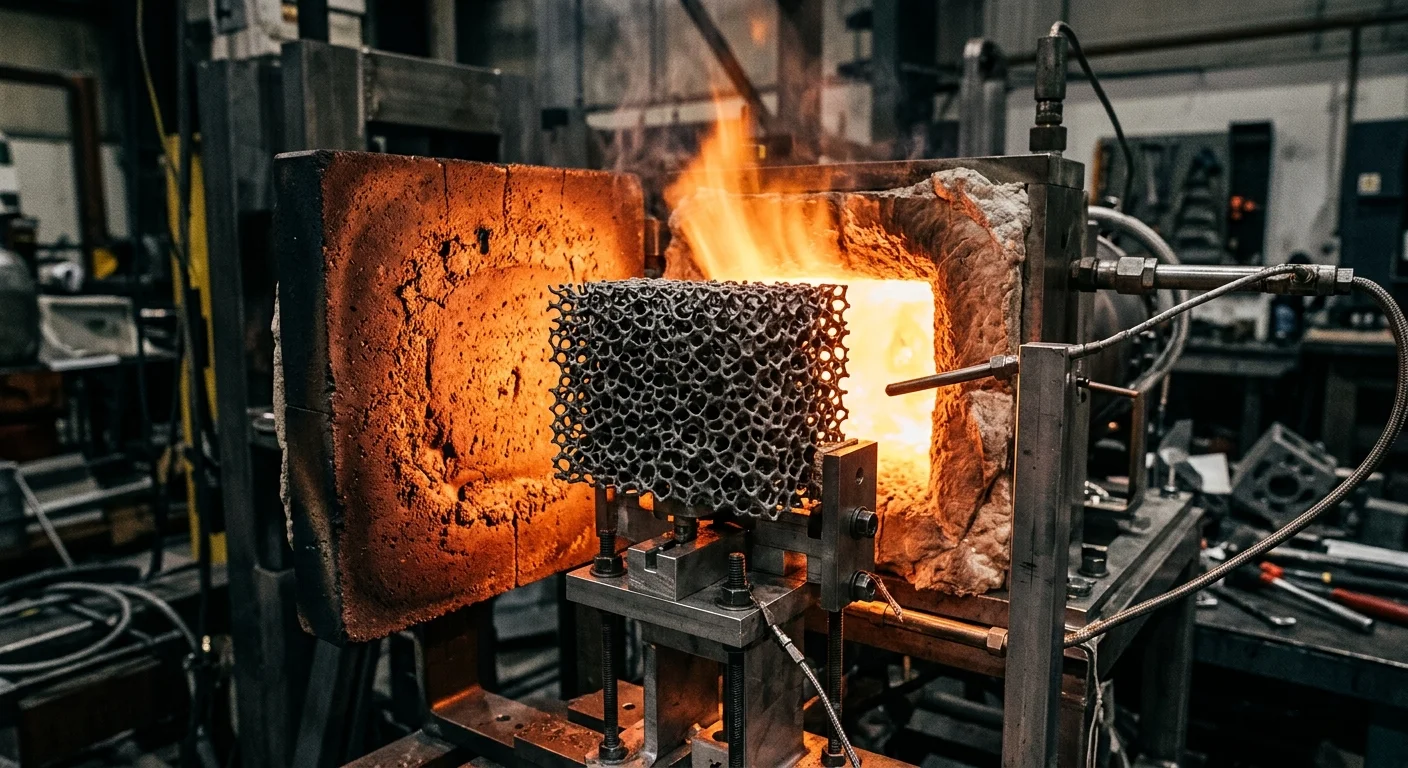
Ceramic foam doesn’t look like much — a lightweight, porous block that could pass for a kitchen sponge. But it handles some of the toughest jobs in modern manufacturing.
It filters molten metal at temperatures that would destroy conventional materials. It supports catalysts in high-pressure chemical reactors. It absorbs combustion gases in industrial exhaust systems.
Knowing the main applications of ceramic foam in foundry and industry matters. It’s the difference between picking a material that holds up and one that solves your engineering problem.
This guide covers every major use case — from metal casting floors to aerospace thermal barriers. Use it to find which type fits your application.
What Are The Main Applications Of Ceramic Foam In Foundry And Industry?
The ceramic foam market hit USD 441.7 million in 2023 — and it’s still growing. That number reflects a simple reality: this material fixes real problems across many industries.
Here’s where ceramic foam does the work:
-
Molten metal filtration — pulls out inclusions and slag before casting. Foundry engineers consider it essential.
-
Investment casting molds and cores — alumina ceramic foam shapes complex metal parts with high precision.
-
Industrial furnace and kiln insulation — reduces heat loss in high-temperature equipment operating above 1500°C.
-
Heat exchangers — strong chemical resistance combined with thermal stability means a long service life.
-
Pollution and emission control — covers air, water, and industrial exhaust treatment needs.
-
Automotive catalyst systems — silicon carbide foam boosts combustion efficiency in burners and exhaust systems.
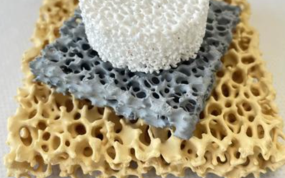
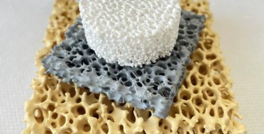
Four materials handle most of these jobs: silicon carbide, aluminium oxide, titanium oxide, and zirconium oxide. Each one fits a specific temperature range and chemical environment. So you pick based on what your process actually demands.
The market is projected to reach USD 483.2 million by 2027. That growth ties closely to rising demand in Metal casting and thermal processing. Both are industries where a material breakdown is simply not acceptable — and ceramic foam keeps proving it can handle the pressure.
What Is Ceramic Foam and Why Its Structure Makes It Useful
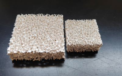
Skip the industrial jargon. Ceramic foam is a block of ceramic that is, at its core, made of air.
Up to 94–96% of its volume is empty space — a three-dimensional web of interconnected pores held together by dense ceramic struts. That structure is not a compromise. It is the entire point.
The pores range from 10 micrometers to 5 millimeters in diameter. Total porosity sits between 75% and 96%, depending on the application. The full structure can handle temperatures up to ~1700°C without breaking down — chemically or physically.
Here is why that combination matters:
-
Open-cell, reticulated structure — all pores connect. Fluid moves through with low pressure drop. The winding path inside forces the fluid to contact the ceramic struts. That contact is where filtration happens. That contact is where catalysis happens.
-
Enormous internal surface area — fine struts packed into a small volume create a vast contact zone. More surface area means more filtration sites, more catalytic activity, and more heat transfer.
-
Dense ceramic walls carrying the load — the strut network delivers real compressive strength, even though most of the material is air. It does not shatter all at once. It fails strut by strut — controlled, predictable, and useful.
-
Air-filled voids blocking heat transfer — thermal conductivity drops fast when 94–96% of your material is insulating air. The ceramic handles the temperature. The air handles the heat loss.
The manufacturing process controls all of these properties. The most common method is the polymer foam replica process. It starts with a polyurethane foam template. A ceramic slurry coats the foam. Heat burns out the polymer. What remains gets sintered into its final form. The ceramic geometry mirrors the original foam with high precision. Change the template, and you change the pore size. Adjust the slurry loading, and you adjust the strut thickness.
That level of structural control lets ceramic foam act as a molten metal filter, a catalyst substrate, a thermal insulator, and an acoustic damper — sometimes all within the same industrial facility.
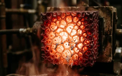
Molten Metal Filtration in Foundries (The Primary Application)
Every casting defect has an origin story — and most of them start with something invisible in the melt.
Oxides. Refractory fragments. Sand particles torn loose from mold walls. These inclusions travel with the molten metal. They settle into the solidifying casting. Then they show up later as cracks, porosity, and failed pressure tests. molten metal filtration is the fix. And ceramic foam is the tool most foundries reach for first.
How the Filtration Works
A ceramic foam filter doesn’t just block particles — it forces the melt to work through it. The open-cell structure creates a winding path through thousands of interconnected pores. Molten metal pushes through that maze. Two things happen as it does:
-
Depth filtration captures inclusions — both indigenous (oxides, spinels, alumina films formed inside the melt) and exogenous (refractory debris, sand, ingot-derived particles).
-
Flow calming cuts turbulence at the gate. This promotes laminar flow, which stops already-separated inclusions from getting back into the stream.
You can see the results in real numbers: lower scrap ratios, better surface finish, improved pressure tightness, and higher yields. In superalloy and secondary aluminium operations, this approach is now standard procedure before every cast.
Matching Filter to Metal
Not every filter fits every pour. You pick the material based on the alloy:
-
Aluminium foundries (gravity, die casting, low-pressure, squeeze cast): alumina or silicon carbide CFFs, rated for molten aluminium at 800–900°C. Single-use, installed in launders or mold runners — placed as the last in-line metal treatment before the casting station.
-
Steel and iron foundries: zirconium-based ceramic filters, built for high pouring temperatures and thermal shock. They target oxide compounds and refractory debris common in ferrous pours.
-
High-temperature ferrous and non-ferrous: Maxsil HS-3000 silica fiber screens — 96% amorphous silica, phenolic-resin coated, rated to 3000°F (1620°C). One thing to note: they carry a 10–25% pour rate reduction versus unfiltered gating. Adjust your gate cross-section to compensate.
The Placement Decision
Where you put the filter changes what it does. Filters placed close to the casting cavity — in-gates on ceramic shell molds — smooth flow into thin sections and cut non-fills. Filters placed further upstream handle higher flow rates but give you less control over last-second turbulence.
For complex thin-wall castings, go small and high-ppi near the cavity. For heavy sections with high throughput, use larger, lower-PPI filters upstream.
The cost math is simple. Ceramic foam Filters are single-use. But defect reductions of 20–50% tied to inclusions offset that cost fast — fewer re-melts, less finishing work, shorter inspection cycles.
Investment Casting, Molds, and Core Applications in Foundries
Precision in casting doesn’t happen by accident. It gets engineered into the mold before a single drop of metal moves.
Investment casting with ceramic foam molds delivers dimensional tolerances of ±0.1–0.25 mm for the first 25 mm. Sand casting sits in the coarser IT13–IT15 range. That’s a meaningful gap. Surface roughness comes in at Ra ≈ 1.6–6.3 μm as-cast. Add fine zircon or alumina face coats, and aerospace components reach Ra ≈ 1.6–3.2 μm. Sand casting? You’re looking at Ra ≈ 6.3–25 μm. The difference is substantial.
Ceramic Cores: The Internal Geometry Problem
Wall sections down to 0.5–1.5 mm are achievable. Thin walls, though, are half the challenge. The other half is internal geometry — cooling passages, oil galleries, hollow turbine blades. That’s where ceramic cores come in.
Ceramic cores act as internal molds during the pour. They hold up against metal temperatures reaching ~1600°C. After casting, foundries remove them through caustic leaching (8–24 hours) or mechanical break-out. Alignment matters here. A misaligned core causes wall-thickness variation beyond ±0.5 mm — and that’s a direct scrap ticket. So foundries check placement with X-ray or CT before the pour starts.
Binder-jet 3D-printed ceramic cores have pushed what’s possible further. Serpentine cooling channels in turbines and pump housings — the kind of geometry conventional tooling can’t produce — are now standard. These aren’t edge cases. They’re routine production.
Ready-to-Pour Monolithic Shells
Printed monolithic ceramic shells with integrated internal cores go straight to foundries, ready to use. The foundry’s job shrinks to three steps:
-
Preheat
-
Pour
-
Knockout
No wax tooling. No shell room. Lead times on complex castings drop by several weeks. For impellers, oil pump housings, and fluid-handling components, that kind of schedule compression is a real advantage.
Fine investment shells also cut machining requirements by 30–70% compared to sand-cast equivalents. The biggest savings come where internal cores net-shape cavities that would otherwise need extensive post-processing.
Gas and Exhaust Filtration in Industrial Emission Control
Raw industrial exhaust carries a cocktail of problems. Particulate matter at 10–5,000 mg/Nm³. SO₂ pushing 3,000 mg/Nm³ from coal-fired sources. NOx running up to 1,500 mg/Nm³. Regulators in OECD countries want stack emissions below 5–30 mg/Nm³ for PM. That gap — between what exits the process and what regulators allow at the stack — is exactly where ceramic foam earns its place.
Where Ceramic Foam Fits the Stack
Ceramic foam doesn’t replace scrubbers or SCR units. It works within them. It acts as a catalyst substrate, a particulate pre-filter, and a flow conditioner. Each role helps downstream systems run better.
In catalytic oxidation systems, Silicon Carbide ceramic foam serves as the support structure for VOC destruction catalysts. These systems operate between 250–400°C. They reach >95–99% destruction efficiency for hydrocarbons and chemical vapors. The foam’s open-cell structure keeps pressure drop low. At the same time, it maximizes gas-to-catalyst contact surface. That same geometry drives its effectiveness in molten metal filtration — here, it does the same job at lower temperatures and against different chemistry.
For NOx reduction, ceramic foam substrates support SCR catalyst beds. These beds are built to hit >80–95% NOx reduction. They target ammonia slip below <2–10 ppmv at the stack. Uniform pore distribution across the foam face keeps NH₃/NOx distribution within ±10% uniformity — the precision that high-conversion SCR requires.
This material holds up where others fail. It handles sustained thermal cycling, aggressive gas streams loaded with harsh chemicals, and the constant mechanical stress of continuous industrial operation.
Thermal Insulation in High-Temperature Industrial Equipment
Heat is relentless. At 650°C / 1200°F and above, conventional insulation doesn’t degrade gradually — it fails completely.
That’s where ceramic foam takes over as a serious industrial insulator. Think about the range of equipment involved: furnaces, kilns, boilers, industrial ovens, heat exchangers, turbines, incinerators. All of these run sustained high-temperature cycles. All of them need insulation that holds up where conventional materials break down.
Here’s how the materials compare by temperature band:
|
Material |
Max Rating |
Thermal Conductivity |
|---|---|---|
|
Mineral wool |
649°C |
0.032–0.044 W/m·K |
|
Ceramic fibre |
1260–1400°C |
~0.12 W/m·K |
|
Microporous silica |
1600°C |
0.021–0.034 W/m·K |
Microporous silica-based insulation has the lowest conductivity in this comparison. Ceramic foam performs in that same high-output tier — at extreme temperatures where other materials can’t compete.
The engineering case is clear. Better insulation delivers real results:
-
Maintained process temperatures — no need for constant energy input to compensate for heat loss
-
Reduced energy loss and lower utility costs over time
-
Worker protection from dangerous surface temperatures in active equipment zones
-
Fire and noise reduction across heavy industrial environments
For equipment running above 1000°F, ceramic hot-side insulation is the standard specification. Above 1800°F, ceramic and silica-based systems are the practical choices available.
Catalyst Supports in Chemical and Petrochemical Processing
Petroleum refining runs on catalytic processes. Every barrel cracked, every aromatic separated, every sulfur compound stripped — catalysts drive all of it. And every catalyst needs something to sit on.
That’s the support’s job. It holds the active phase in place, spreads it across a large surface area, and keeps it stable through thousands of hours of heat cycling and chemical exposure. Ceramic foam — alongside alumina, silica, and zeolite-based materials — fills this role in some of the toughest fixed-bed environments in industry.
What the Support Does
A catalyst support isn’t just inert scaffolding. It shapes how well the active metal performs.
Surface area is the first variable. γ-Al₂O₃ delivers 150–300 m²/g — the standard benchmark for hydrotreating and hydrocracking supports. Silica runs higher at 200–800 m²/g. Mesoporous grades like MCM-41 and SBA-15 push 600–1000 m²/g for fine chemical applications. Zeolites (Y, ZSM-5) reach 400–900 m²/g and lead FCC and aromatics operations. Their shape-selective micropores (0.5–0.8 nm) filter which molecules reach the active site and which don’t.
Pore structure matters just as much as surface area. Hydroprocessing supports target 6–20 nm mesopores with pore volumes of 0.4–0.8 cm³/g. Wide enough for heavy feed molecules to diffuse in. Tight enough to hold mechanical integrity under bed loading.
Matching Material to Process
Support selection follows the process envelope — not the other way around:
-
Hydrotreating (300–380°C): Co-Mo or Ni-Mo on γ-Al₂O₃ or alumina-silica, surface area 150–250 m²/g, mesopore diameter 10–15 nm. This setup runs across every major refinery.
-
Hydrocracking (350–430°C): Ni-W on silica-alumina or zeolite Y supports. The support’s Brønsted and Lewis acidity does part of the cracking work.
-
Reforming and aromatization (480–520°C): Pt or Pt-Sn on chlorided alumina or zeolite Y. At these temperatures, carbon supports burn off. Inorganic oxides and ceramics are the practical choices here.
-
Fine chemical hydrogenation: Pd, Pt, or Ru on activated carbon (500–1500 m²/g) where high metal dispersion and low surface acidity are top priorities.
Ceramic Supports in Fixed-Bed Reactors
Ceramic catalyst support media — balls, saddles, rings, extrudates — come in 3–50 mm diameters. Size depends on reactor dimensions and acceptable pressure drop. Suppliers like CoorsTek build these for chemical and petrochemical environments where corrosive feeds and high temperatures rule out organic binders and weak materials.
Mechanical strength is non-negotiable. Large ceramic support balls for fixed-bed petrochemical reactors need compressive strengths above 5–15 kN per piece. Smaller extrudates for hydrotreating require crush strengths of 30–150 N per pellet. These aren’t safety margins — they’re floor values. A crushed support bed causes channeling, pressure drop spikes, and early catalyst replacement.
The selection process comes down to five steps:
-
Define the temperature and chemical range
-
Set pressure drop limits
-
Specify surface area and pore structure
-
Match chemical functionality to the reaction type
-
Verify mechanical properties against bed height and loading method
Get all five right, and the support runs steady and trouble-free for years.
Burners, Heat Exchangers, and Combustion Intensification
Conventional industrial burners waste 15–30% of their fuel input before a single useful BTU reaches the load. That’s not a rounding error — it’s the baseline inefficiency ceramic foam-based heat exchanger systems are built to fix.
The mechanism is air preheat. Regenerative burner systems use ceramic checker media with 200–600 m²/m³ of specific surface area. This captures heat from outgoing flue gas and moves it into incoming combustion air. The results are substantial:
-
250–300°C air preheat: 3–8% fuel savings
-
400–500°C preheat: 10–25% fuel reduction, measurable combustion intensity gain
-
700–800°C preheat (regenerative systems): 30–50% fuel savings in high-temperature furnaces
In a furnace retrofit, tripling the heat-transfer surface area pushes combustion air preheat from ~250°C to 750–800°C. Stack temperatures drop by 200–300°C as a result.
Combustion Intensification: The Practical Levers
Higher preheat raises adiabatic flame temperature. Preheating by 300–400°C adds 150–250 K to flame temperature. Radiant heat transfer scales with T⁴, so a 5% flame-temperature gain delivers 20–25% more radiative heat flux to the load surface. That’s a significant output gain from a single process change.
For NOx control at high preheat levels, staged burners with internal flue-gas recirculation keep emissions below 100–200 mg/Nm³. That’s well under the >300 mg/Nm³ you typically see with conventional high-preheat setups.
One design constraint to flag early: air preheat above 600–700°C requires special alloys or refractories at the burner tile. Plan for that upfront — not during commissioning.
Aerospace and Advanced Structural Applications
Weight is the enemy in aerospace. Every gram saved means more range, more payload, or lower fuel cost. That pressure pushes the industry toward materials that do more with less.
Ceramic foam delivers on this through its multifunctional load-bearing potential. One component can insulate, filter combustion gases, and absorb structural impact — all at once. That’s exactly the performance-to-weight logic aerospace engineers are chasing.
Here are the key priorities driving advanced structural material selection today:
-
Structural efficiency and survivability — ceramic foam fails in a controlled way (strut-by-strut, not sudden fracture), which suits blast and impact applications
-
Lightweighting — high porosity keeps mass low without giving up thermal performance
-
Repairability and field maintainability — modular ceramic foam inserts allow in-situ replacement in aircraft thermal management systems
-
Next-generation multifunctional material systems — ceramic foam works as both a structural and functional material at the same time
For aerostructure teams validating new material systems, the workflow is straightforward. First, build a property and performance test database. Then iterate through digital engineering. Finally, validate damage tolerance under real load conditions before flight qualification.
Biomedical and Specialty Applications
Ceramic foam has found its place in medicine — starting with scaffolding.
Bone tissue engineering needs a specific type of material. It must mimic cancellous bone: porous, biocompatible, strong enough to bear load, and open enough for cells to grow into. Hydroxyapatite ceramic foam meets all of these needs. Its interconnected pore structure matches the 100–500 μm range that bone ingrowth requires. This gives osteoblasts a surface to attach to and blood vessels a clear path to follow.
Ceramic foam also goes beyond implants. It works as a filtration membrane in biomedical fluid processing. It also acts as a substrate in controlled drug-release systems. There, precise pore sizing controls how fast substances diffuse through the material.
These aren’t high-volume markets. But they are high-precision ones. Material failure here isn’t measured in scrap rates — it’s measured in patient outcomes. That’s a very different standard.
Acoustic Absorption and Environmental Noise Control
Industrial noise is measurable, predictable, and — with the right material — controllable.
Ceramic foam’s open-cell pore structure traps sound energy the same way it traps heat and particulates. Sound waves travel through the strut network. Friction converts that acoustic energy into small amounts of heat. The porous, interconnected geometry does all the work.
The practical numbers are modest but real. In reflective industrial spaces, ceramic foam absorption panels deliver 2–6 dB noise reduction. Boost total absorption by 300%, and you gain 5 dB more. That gain is strongest where baseline absorption starts low.
Where absorption works:
– Speech noise and crowd chatter
– High-frequency reflections in hard-walled industrial enclosures
Where it falls short:
– Low-frequency bass and mechanical vibration
– Impact noise and sound passing through shared walls
Those problems need mass-loaded blocking or structural isolation — absorption alone won’t solve them.
The decision rule is straightforward. Reverberant buildup inside a space? porous ceramic absorption panels are your first move. Noise escaping to nearby areas or outdoor communities? Add barriers and airtight separation on top of the absorption layer.
For outdoor industrial sites — utilities, data centers, BESS installations, energy facilities — active noise control (ANC) systems pair well with ceramic absorption. They generate equal and opposite sound waves in real time. This suppresses noise before it reaches nearby communities.
How to Select the Right Ceramic Foam: Material and Porosity Matching Guide
Two variables drive every ceramic foam selection: material composition and porosity level. Get both right, and the foam runs for years. Get either one wrong, and you’re replacing it ahead of schedule — and over budget.
Start with porosity:
-
90–96% void space → lightweight, with strong airflow. Best for thermal insulation, catalyst support, acoustic damping, and low-pressure-drop filtration
-
20–80% porosity → denser and stronger. Use this range where mechanical strength or controlled flow resistance is the priority
Then choose cell structure:
-
Open-cell (reticulated) → molten metal filtration, hot gas filtration, catalyst beds, gas distribution — any application where fluid must pass through the foam
-
Closed-cell → insulation-first applications where trapped gas does the thermal work
Then match material to your temperature and chemistry:
|
Material |
Best For |
|---|---|
|
SiC |
Thermal shock resistance, demanding filtration |
|
Alumina |
Chemical stability, sustained high heat |
|
Zirconia |
Extreme temperature durability |
|
Mullite/Cordierite |
Balanced thermal management |
One rule overrides everything else: size your selection against maximum continuous operating temperature plus thermal cycling — not just the nominal temperature. ceramic foams can handle up to 1600–1700°C. But cycling stress — repeated expansion and contraction — is what breaks them down fast. Don’t just check peak temperature. Check how often your process cycles through it.
Conclusion
Ceramic foam isn’t a one-trick material. It’s a reliable workhorse that performs in some of the toughest environments industry has ever built. It pulls inclusions from molten aluminum at 700°C. It silences industrial exhaust. It supports catalytic reactions. It even works alongside living bone tissue. Few engineered materials cover that kind of range.
The reason is always the same: that open, interconnected pore structure does what solid materials simply can’t.
You’ve read this far — so you’re not here out of curiosity. You have a real challenge on your desk right now. A filtration issue. A thermal problem. A design constraint that needs a solution.
So skip the extra reading. The real next step is matching the right material grade and pore rating to your actual operating conditions.
Start there. The right ceramic foam, specified well, doesn’t just fix the problem. It makes everything downstream run better too.