Every casting engineer knows this tradeoff well: filter out more inclusions, or keep your melt flowing fast enough to fill the mold before it freezes.
Screens look simple. A flat barrier catches what it catches. But that single-plane design lets a lot of contamination pass straight through.
Ceramic foam Filters work differently. To understand why, you need to look at the physics of how particles separate from molten metal.
This breakdown of depth filtration vs. surface filtration cuts through the marketing noise. You’ll see where screens fall short, why the tortuous flow path changes everything, and how to match the right filter geometry to your real-world pour conditions.
What Is Depth Filtration and How Does It Capture Particles?
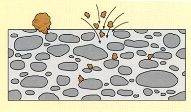
Depth filtration follows one structural rule: the filter medium must be thick enough to trap particles inside it — not just block them at the surface. In industrial use, that means the media thickness must be at least 100 times the target particle diameter. A 5 µm inclusion needs 500 µm of filter depth to get caught. A 10 µm particle needs a full millimeter. Scale that up, and it becomes clear why a 50 mm ceramic foam block works — and why a 1 mm screen cannot.
Five Mechanisms Working in Parallel
Depth filtration beats surface filtration for more than just geometric reasons. It runs multiple capture mechanisms at once as a particle moves through the medium:
- Mechanical interception — the twisted pore network blocks particles too wide to pass through local gaps. This happens deep inside the filter, not just at the entry face.
- Inertial impaction — heavier particles can’t follow sharp bends in the flow path. They break away from the flow and embed into pore walls.
- Van der Waals adhesion — fine particles that touch internal surfaces bond through molecular attraction and stay fixed. Size exclusion plays no role here at all.
- Particle bridging — captured particles build up across pores, narrowing the effective pore size over time. This improves capture of smaller and smaller material further down the filter.
- Adsorptive retention — soft contaminants like oxide films and gel-phase inclusions push into the fibrous matrix and lock in place.
No single mechanism does all the work. That’s the point. One misses a particle, another grabs it.
The Dirt-Holding Advantage
Depth filters distribute captured material across the full volume of the medium. That’s why they hold 2–3 times more contaminant mass than comparable surface filters before flow restriction becomes an issue. Surface filters clog fast — all the captured material piles up at one plane, and pressure drop spikes hard. Depth filters spread that contamination through their full thickness. The pressure curve stays flat longer, and the filter stays useful for a longer service life.
What Is Surface Filtration and How Do Screens Work?
Surface filtration runs on one rule: if it’s bigger than the hole, it stops. If it isn’t, it passes through.
That’s not an oversimplification. That’s the entire mechanism.
A screen, a wire mesh, a perforated plate — these are all surface filters. Every pore sits in a single plane. Metal flows through, and particles face a binary decision at that plane: go or no-go. Particles larger than the aperture get blocked and pile up on the upstream face. Everything smaller flows straight into your mold, untouched.
The Numbers Behind the Cut-Off
Industrial woven wire screens are specified by mesh count and wire diameter. A 100-mesh stainless screen — an industry benchmark — delivers openings of about 150 µm. Perforated metal strainers punch holes between 0.5–5 mm for coarse industrial applications. Both designs share the same hard ceiling: geometric sieving defines where retention starts and stops.
Initial capture efficiency for surface filters sits at 50–70% for the target particle size range. That number climbs toward 100% once a filter cake builds up on the surface. Captured particles form their own tight barrier layer — and it gets tighter over time.
Where the Cake Becomes a Problem
That cake formation looks like a win. In practice, it’s a liability.
As the cake densifies, flow resistance climbs. Pores constrict. Pressure drop rises fast across a surface designed to block contamination — not store it. Screens on high-inclusion metal streams can go from clean to critically fouled in minutes. Cleaning is simple — backwash, scrape, replace — but it’s frequent, and it cuts into production time.
Worse, the cake only helps with particles near or above the original aperture size. Micro-inclusions below 10–20 µm pass right through, no matter how thick the cake gets. For screens with openings in the 100–500 µm range, fine oxide films and sub-20 µm particles are a real problem. These are the particles that damage fatigue strength and leak-tightness. Yet screens can’t see them at all.
What Screens Do Well — And Where They Stop
Screens earn their place in filtration systems. They’re low cost — basic stainless screen elements often run less than 25–50% of the price of comparable depth cartridges. The cut-off is predictable. Installation and cleaning are simple. For coarse, well-characterized contaminants where the maximum particle size is known and consistent, surface filtration is fast, cheap, and reliable.
But surface filtration has a ceiling. It gives you a single interception plane, no redundancy, and no way to catch anything below its aperture. Tear one wire, crack one section, and that geometric cut-off is gone — with nothing inside the medium to catch what slips through.
That’s the structural gap depth filtration was built to close.
Why Ceramic Foam Filters Are a Form of Depth Filtration
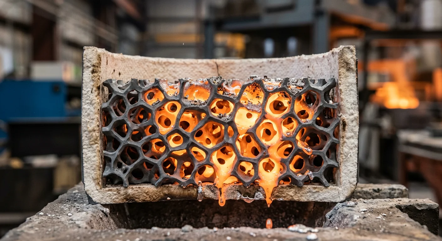
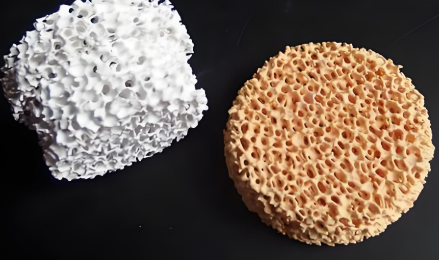
The classification isn’t arbitrary. Ceramic foam filters earn the “depth filtration” label through their physical structure. The filter body is a three-dimensional, open-cell refractory block. Molten metal passes through the entire matrix — not just past a single barrier plane.
That structure uses Refractory Ceramics matched to the alloy: – Alumina (Al₂O₃) for aluminum – silicon carbide (SiC) for cast iron – Zirconia (ZrO₂) for steel
Open porosity sits at 80–90%. That’s not a coincidence. It’s what makes depth capture work. You get a vast internal surface area packed into a compact block — ready to intercept, deflect, and hold inclusions across the full filter thickness.
PPI as a Depth-Filtration Design Variable
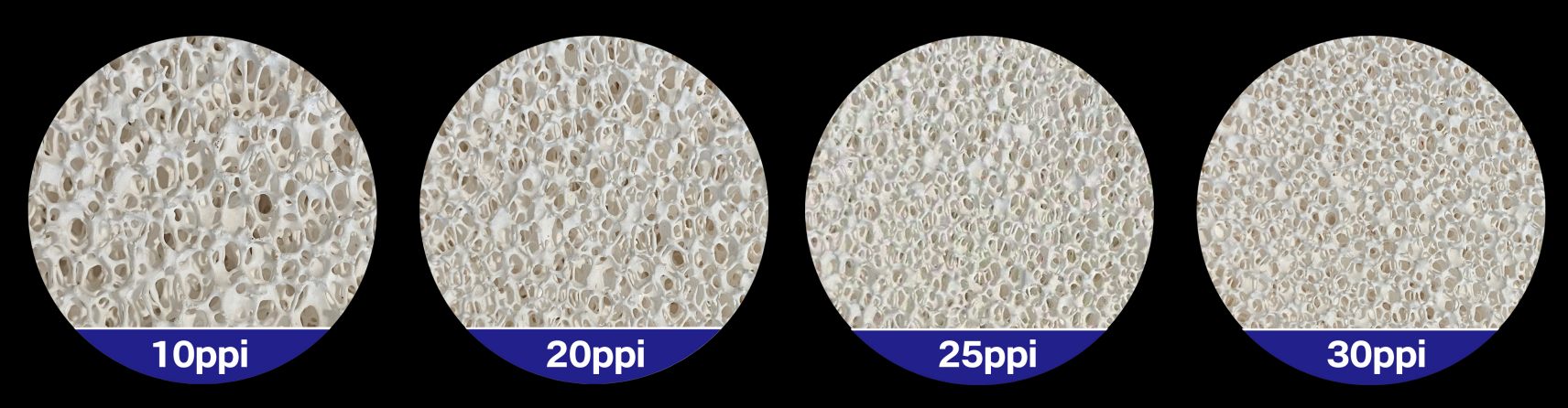
Commercial ceramic foam filters are specified in pores per inch (PPI), with a range of 10 to 50 PPI. This is a depth-filtration design parameter. It’s not just a size spec.
Higher PPI gives you smaller pore windows. You get more direction changes per unit length and finer inclusion capture — at the cost of higher flow resistance. Lower PPI gives you larger windows, higher permeability, and coarser filtration suited to faster pours. The balance between pressure drop and capture efficiency is controlled through pore geometry alone. That’s a different design logic than picking a mesh aperture size.
How the Tortuous Network Does the Work
Metal enters the filter. The 3D channel network takes over from there. Flow direction shifts at every turn. Metal rounds internal corners. At each bend, heavier inclusion particles break away from the flow path and hit ceramic strut surfaces — Van der Waals adhesion holds them there. Inclusions that survive one contact hit the next strut, and the next.
Particles smaller than the nominal pore window get captured throughout the full cross-section of the filter. They don’t need to be larger than a pore to get caught. That’s what separates depth filtration from surface filtration — and ceramic foam performance data backs this up. Filtration efficiency reaches up to 95% for aluminum melt, with capture of suspended inclusions as small as tens of micrometers.
Over time, captured inclusions build up inside the foam volume. They form deposits distributed through the depth — not a single surface cake. The filter keeps working. Flow restriction builds at a gradual rate. That’s the operational signature of a true depth filter.
Head-to-Head Comparison: Ceramic Foam Filters vs. Screens Across 6 Key Performance Dimensions
Six dimensions. One clear winner. Here’s what the data shows.
1. Particle Capture Location
Screens capture inclusions in a single plane — the upstream face. Once that face loads up, the open area collapses. Bypass risk climbs fast.
Ceramic foam filters work across the entire 3D matrix. Inclusions stick to strut surfaces and settle into slow-moving zones spread through the full depth. The internal surface area is several times greater than a flat screen of the same front size. That’s not a small improvement. It’s a structural advantage built into the geometry itself.
2. Particle Size Range
This is where screens hit their hard ceiling.
Typical foundry mesh openings run 500–1000 µm. Screens catch what’s above that threshold. Everything below — sub-100 µm fine oxides, the particles that destroy fatigue strength and leak-tightness — passes straight through. Untouched.
Ceramic foam filters work in a far smaller size range:
– Standard alumina CFF: >90% efficiency for inclusions ≥20 µm
– Depth capture mechanism: holds inclusions down to 10–20 µm, even below nominal pore size
– High-efficiency grades: removal down to around 5 µm has been documented
The sub-20 µm range is where porosity, fatigue failures, and leak defects start. Screens can’t reach it. Ceramic foam filters do — consistently.
3. Dirt-Holding Capacity
Screens pile all captured material onto one surface plane. That plane fills. Pressure spikes hard and fast. In metal streams with high inclusion loads, this can happen within minutes.
Ceramic foam filters spread captured inclusions through the full pore volume. The pressure curve rises gradually. The filter keeps working. Size it right — filter face area at 2–4× the gating choke area — and a ceramic foam filter handles a full ladle or furnace pour without any intervention. No mid-pour swap. No process interruption.
4. Pressure Drop and Flow Stability
Screens start with low resistance. That advantage disappears the moment surface caking begins. Flow diverts. Metal finds unintended paths. Misruns and cold shuts follow.
Ceramic foam filters need a bit more initial head pressure. You control that through PPI selection:
– 10–20 PPI: high flow, coarser filtration, dirtier alloys
– 30 PPI: standard grade, the production workhorse
– 40–60 PPI: aerospace and thin-wall applications where cleanliness outweighs flow cost
That initial head stays stable throughout the pour. Flow stays laminar. No sudden spikes. No bypass events.
5. Operational Lifespan Per Pour
Ceramic foam filters are single-use by design — and that’s a feature, not a limitation. One filter, one heat, predictable performance from start to finish. Scrap analysis stays consistent heat-by-heat.
Screens are intended to be reusable. In practice, thermal shock and slag build-up force mid-process changes anyway. Filtration quality shifts during the pour. Defect rates vary. Process control suffers.
6. Cost vs. Performance
Screen unit cost is lower. That’s the whole argument for them, and it’s a short argument.
Run the real numbers:
- Alumina CFF use in aluminum foundries cuts scrap by 15–40% compared to strainer practice
- For aerospace and automotive structural castings, switching from screens to ceramic foam filters produces a 50–90% drop in inclusion-related defects — well documented across the industry
- Cut scrap from 8% to 4% with CFF, and the savings on rejected castings exceed filter cost by 3–10× per heat
Screens cost less per piece. Ceramic foam filters cost less per accepted casting. On the production floor, that second number is the one that matters.
The Core Reason Ceramic Foam Filters Outperform Screens: The Tortuous Flow Path Advantage
The geometry tells the whole story.
A screen gives molten metal one direction to travel: straight through. A ceramic foam filter forces metal to fight for every millimeter. It splits, turns, and recombines through a three-dimensional maze of interconnected voids and ceramic struts. That forced detour is not a design inconvenience. It is the entire mechanism.
Three Mechanisms, One Architecture
Screens do one thing: sieve. Ceramic foam filters run three capture processes at once:
- Mechanical sieving — large inclusions above the pore window get blocked at the inlet face
- Physical adsorption — finer particles contact strut surfaces and bond through surface energy forces. They stack in multilayer deposits across the ceramic area, without any sorting or selection
- Cake filtration — captured material builds a secondary micro-porous layer. This layer tightens the effective pore size deeper into the filter. It catches finer and finer inclusions as the pour continues
No single mechanism carries the load. Each one catches what the last one missed.
Why Direction Changes Are the Key Variable
At every bend in the tortuous network, inclusion particles hit the same physics problem: their inertia cannot follow the streamline. Heavy particles — oxide clusters, bifilm fragments, intermetallic compounds — break from the flow path and strike the nearest ceramic strut. The filter packs 85–90% open porosity into a compact reticulated block. That gives inclusions far more chances to collide with solid surfaces than a flat screen ever could.
So inclusions down to 10–20 µm get captured inside the foam volume — well below nominal pore size. A comparable mesh just lets them pass straight through.
The Bypass Problem That Eliminates the Advantage
One design detail matters more than PPI selection: sealing. Experimental data shows bypass gaps around a ceramic foam filter can cause up to 60% underestimation of actual pressure drop. In production, any gap around the foam drops filtration performance back to screen level. The tortuous path only works when every drop of metal is forced through it.
Practical Selection and Installation Factors That Determine Real-World Performance
Choosing the right ceramic foam filter is half the job. Seating it right, priming it, and matching it to your metal condition — that’s where filtration efficiency either shows up in your castings or doesn’t.
PPI Selection: Match the Filter to the Metal
PPI is not just a cleanliness spec. It’s a pressure drop, flow rate, and inclusion load decision — all packed into one number.
Here’s how the grades break down in aluminum foundry practice:
| PPI | Approx. Pore Size | Best For | Min. Head Required |
|---|---|---|---|
| 10 | 2.0–3.0 mm | Dirty remelt, ingots, sand-heavy returns | 75–100 mm |
| 20 | 1.5–2.0 mm | Standard sand castings, moderate inclusion loads | 75–100 mm |
| 30 | 0.9–1.5 mm | Cylinder heads, compressor housings, structural fatigue parts | 100–150 mm |
| 40 | 0.6–1.0 mm | Thin-wall chassis parts, wheels, high-cleanliness requirements | 125–175 mm |
| 50 | 0.4–0.7 mm | Aerospace alloys, investment casting, critical thin-wall runners | ≥150–200 mm |
Two rules worth locking into your process:
- Dirty charge with complex geometry → run two stages. A 10–20 PPI coarse filter upstream, 30 PPI downstream. The coarse filter protects the fine one from early bridging.
- Never run 40–50 PPI if your inclusion load is unknown or your metallostatic head is under 100–125 mm. Bridging and freeze-off risk rises fast. You’ll get an incomplete fill — and no clear data on why.
Seating and Sealing: The Gap That Kills Filtration
Here’s a number that should shift how you approach installation. A continuous 1 mm circumferential gap around a 50×50 mm filter creates a bypass cross-section of 8×10⁻⁶ m². The filter’s effective open area is only 250–375 mm². That small gap pulls in a much larger share of total flow than you’d expect. Industry operators report 10–20% bypass from filters that aren’t seated well.
The casting looks clean on the surface. X-ray tells a different story.
Installation rules that prevent this:
- Target zero visible light between the filter edge and bowl wall after seating
- Use 2–5 mm compressible fiber paper or gasket board to cover dimensional tolerances
- Bowl land width must be ≥5–10 mm around the full perimeter
- Set cavity depth at 1–3 mm less than filter thickness — this creates compressive seating as the mold closes
- Reject any mold where the gap exceeds 0.5 mm at any point, or where the filter shifts under light finger pressure
Two failure signs worth knowing. Oxide trails coming from one corner of the gating mean there’s a gap at that corner. Castings that look clean on the surface but fail on mechanical testing or X-ray point to bypass somewhere in the system.
Priming and Metallostatic Head
A ceramic foam filter doesn’t open like a valve. Metal needs to build enough head pressure to push through viscous resistance and surface tension inside the pore network. For aluminum, that means:
- 10–20 PPI: reliable priming at 75–100 mm head
- 30 PPI: 100–150 mm head
- 40–50 PPI: often ≥150 mm, especially at low superheat
The physics behind this: at 100 mm head, aluminum at 2,400–2,500 kg/m³ produces 2.4–2.5 kPa of driving pressure. Field data shows 30–40 PPI foam needs 2–4 kPa to prime with consistency. That’s where the 100–150 mm rules come from — not guesswork.
Keep metal superheat at 40–80°C above liquidus for standard aluminum alloys. Drop below that range with a 30–50 PPI filter, and you risk a cold start. Metal freezes inside the foam before the mold fills. Watch for this tell: metal hesitates at the filter, then surges through with turbulence upstream. That’s intermittent priming — a process problem, not a filter problem.
Degassing and Filtration: Two Jobs, Not One
Degassing and ceramic foam filtration solve different problems. Mix them up, and you lose castings.
Rotary degassing targets dissolved hydrogen — pulling it from 0.3–0.4 ml/100 g aluminum down to ≤0.1 ml/100 g under good conditions. Ceramic foam filters target solid inclusions: oxides, refractory particles, sand, carbides. A well-sized and installed CFF can cut inclusion area fraction on PoDFA or LiMCA tests by 50–80%. It does almost nothing for dissolved gas.
Run both, in sequence: furnace → rotary degassing + fluxing → transfer → CFF at launder or mold entry.
Skip degassing and lean on a finer PPI filter instead, and you’ll get castings low in inclusions that still fail on porosity. Skip the filter and lean on degassing alone, and you’ll get sound castings that fail in fatigue from oxide films. Neither replaces the other. Don’t trade one for the other. And don’t cut degassing parameters after installing CFF thinking filtration covers the gas problem — it doesn’t.
Where Screens Still Earn Their Place
Screens aren’t obsolete. They’re limited — and using them well means knowing where those limits sit.
Screens make practical sense for:
- Coarse pre-filtration: catching large dross, furnace skim, and broken refractory before it loads up a ceramic foam filter. Use 3–6 mm openings in the launder or pouring basin, positioned upstream of the CFF.
- Low-criticality, thick-walled castings with clean, well-controlled metal — ingot molds, counterweights, and applications where defect tolerance is genuinely high
- Very high-flow ingot lines where ceramic foam pressure drop would hurt fill
One thing to keep in mind: screens often increase turbulence as metal passes through them. Ceramic foam filters calm flow. For any casting where surface quality, fatigue strength, or leak-tightness matters, that turbulence difference alone pushes the decision toward ceramic foam.
Conclusion
Depth filtration vs. surface filtration — this isn’t a debate. It’s a decision. And it has direct consequences on your cast metal quality, scrap rates, and operational costs.
Ceramic foam filters win because physics demands it. A tortuous flow path captures inclusions across a full three-dimensional matrix. A flat screen only blocks what it can’t pass. That’s a fundamental difference. More contact area means more capture opportunities — and more consistent results.
Still relying on screens for critical casting applications? The performance gap is larger than you think. It’s showing up in your rejects right now.
Next step: Audit your current filtration setup against the six performance dimensions covered above. Ask yourself — where are your screens falling short? That gap is exactly where ceramic foam filtration pays for itself. Often within the first production run.
Choose the filter that works with your melt, not just in front of it.