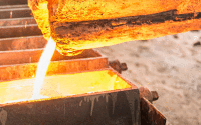
A single microscopic oxide inclusion — invisible to the naked eye — can be the difference between a flawless brass casting and a scrapped part with a hairline crack under load. That’s the quiet threat lurking in molten brass: dross, entrained slag, and complex oxides that form the moment the melt hits air, and that gravity settling alone will never fully catch.
Ceramic foam Filters earn their place in the Gating System here. Understanding how they remove oxides and inclusions from molten brass means getting into the real mechanics — the tortuous pore pathways that trap particles mid-flow, the surface-versus-depth filtration dynamics working together, and the turbulence-taming effect that keeps the melt calm as it fills the mold. We’ll also break down which impurities get caught, which filter types fit which brass alloys, and the operating parameters that separate a filter that works from one that just sits in the runner doing nothing.
Ceramic Filter Working Mechanism: Tortuous-Path Filtration
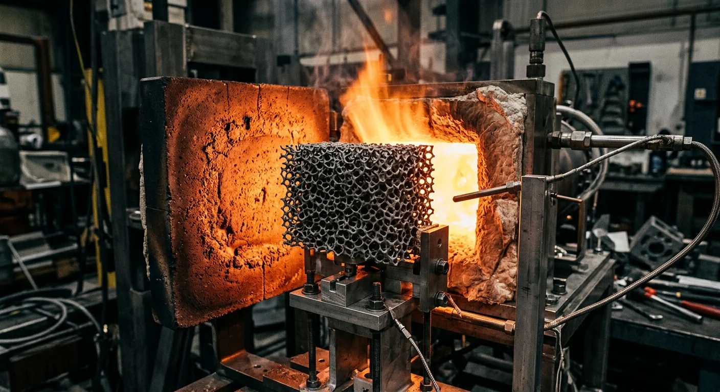
Fluid never moves in a straight line through a ceramic filter. It zigzags. Inside the microporous structure, pores of varying sizes connect and interconnect, forcing the melt to change direction again and again as it pushes through. That maze-like path is exactly why Ceramic filters catch particles far smaller than their labeled pore size suggests. A filter rated at 10 μm can actually trap particles down to about 1 μm in Liquid filtration — and around 0.5 μm when filtering gas. The stated pore size is a starting point.
Three Capture Mechanisms at Work
- Geometric interception: Particles larger than the pore opening get stopped cold, right at the surface or pore mouth.
- Inertial impaction: Mid-sized particles carry enough momentum that they slam into pore walls as the flow bends, sticking there instead of following the fluid.
- Brownian diffusion: The smallest oxide fragments drift off the main streamline entirely, colliding with walls through random motion and getting caught in the process.
As filtration continues, trapped particles build up on the surface, forming a filter cake. This layer actually improves filtration precision over time — but it also raises pressure drop, which is why pulse backflushing gets used to clear accumulated debris and restore flow.
Porosity Matters More Than People Think
Lower filtration speeds combined with higher porosity tend to push particles deeper into the ceramic structure rather than stopping them at the surface. That’s the deep-bed filtration effect.
10 PPI filters have fewer, coarser channels — good for catching larger inclusions but less effective on fine oxides. 30 PPI filters pack in denser, more convoluted pathways, raising contact probability for smaller particles at the cost of higher pressure drop. 20 PPI sits in between, balancing flow rate against capture efficiency for general-purpose brass casting work.
Surface Capture & Depth Filtration Dual Mechanism
Not every inclusion gets caught the same way. Size decides the mechanism, and that distinction matters for anyone specifying a ceramic filter for brass casting.
Surface capture handles the bigger stuff — particles at or above roughly 0.3 µm up to several microns, anything large enough to bump into a pore mouth or fiber surface. Depth filtration takes over for the fine fraction, particularly particles under 0.3 µm, where oxide fragments drift into the internal pore network and settle via diffusion rather than blunt collision.
There’s an awkward middle ground, though. Research on porous media and diesel particulate filters consistently shows a capture efficiency valley around 100–300 nm, sometimes as low as 0.2 at flow rates near 0.8 L/min for particles in the 50–100 nm range. Below 200 nm, Brownian diffusion drives capture. Above 200 nm, interception takes over. This “most penetrating particle size” zone typically sits between 0.1–0.5 µm, often cited around 120 nm in HEPA-grade filtration studies.
Material choice shifts which mechanism dominates:
- Alumina filters build finer, more uniform pore structures with higher surface energy — better suited for surface capture blended with shallow depth filtration.
- SiC filters lean on rigid, high-temperature-stable networks with connected macropores (>50 nm) — stronger for deep filtration under high thermal load, though pressure drop climbs faster once pores clog.
For brass casting specifically, this means matching filter chemistry to expected inclusion size instead of just picking a PPI rating and hoping.
Turbulence Reduction (Laminarization) Effect
Faster isn’t better when molten brass is fighting its way through a runner. Push the flow rate past a critical threshold and the free surface starts churning. That’s when oxide film gets folded into the melt instead of staying on top where it belongs. Synchrotron imaging of metal welds shows that at surface velocities between 0.1–0.5 m/s, when surface tension favors turbulence, oxides get trapped directly into the solidifying structure. Speed up the surface, and you’re stirring in more defects.
Ceramic filters interrupt that chain reaction. Forcing the melt through the pore network breaks it into hundreds of smaller, slower channels and flattens out velocity peaks. Backflow and surface waviness, the two conditions most responsible for re-entraining oxide skins, lose their energy before they can do damage.
Downstream in the mold, you get reduced surface vortexing at the gate, less air and oxide pull-in, more even flow distribution across the runner cross-section, and lower shear near mold walls, which limits the microscale flow instability tied to rough cavity surfaces.
The practical target is controlled flow. Ceramic filters get molten brass there by cutting turbulent kinetic energy before it reaches the casting cavity.
Specific Types of Impurities Removed During Brass Melting
Four types of impurities show up in molten brass, and each one needs a different approach from the filter.
Oxides are the biggest group. Cu₂O and CuO form directly when copper reacts with the furnace atmosphere. Alongside them you get Al₂O₃, SiO₂, SnO₂, FeO, MnO, ZnO, NiO, and FeO·MnO — solid particles with high melting points that resist simple deoxidation and stay suspended as fine dispersoids.
Non-metallic inclusions overlap with oxides but also include sulfides — specifically Cu₂S and CuS. Both are hard, brittle phases that break up the material’s continuity.
Dross and slag form on the melt surface from flux residue, refractory erosion, and deoxidation byproducts. Copper oxide dross, zinc oxide dross, and mixed flux-reaction slag all trap liquid metal as they form, causing composition loss and slag-inclusion defects.
Foreign debris — sand particles, fragments of refractory lining, dust, sludge, crystalline salts, fiber residue — comes in through worn ladles, runners, and tundishes, or gets carried in with recycled scrap.
Why This Matters for Casting Quality
High-hardness oxides like Al₂O₃ and SiO₂ cause fatigue cracking and localized brittle fracture. Sulfide inclusions weaken structural uniformity, leaving pinholes and surface pitting behind.
China’s GB 16487.7-2017 standard limits total inclusions in recycled brass feedstock to 1%, with fine powder contaminants under 2mm restricted to under 0.1%. That tells you how little tolerance brass casting has for these particles.
The Real Impact of Ceramic Filtration on Brass Casting Quality
Numbers don’t lie, and these are the ones that matter. Foundries running ceramic filters on brass and copper-alloy lines are chasing measurable drops in scrap and measurable gains in strength. The data backs them up.
Defect Reduction, Measured
One study tracking surface defects before and after filtration found defect area dropping from 34% to 8.6%, a 74.7% reduction. Surface defects came in 4 times less than unfiltered pours. Grain structure tightened up too, which usually means steadier mechanical properties and fewer parts pulled for rework.
What Copper Alloys Show
Brass-specific data is thin, but copper alloy systems tell a close-enough story. In aluminum bronze, a cousin alloy worth watching, filtration pushed tensile strength up 18%, elongation up 34.8%, and dropped the scrap rate from 23% to 7.5%. Porosity and gas holes shrank noticeably. Density, hardness, and pressure-tightness all moved upward.
Foundry-Wide Averages
Across multiple foundries running ceramic foam filters on production lines, the pattern holds:
- Process yield: up 5–10%
- Scrap rate: down 15–30%
- Tensile strength: up 5–10%
- Hardness: up 5–10%
- Bending strength: up 5–8%
- Machining performance: improved, with less repair work and smaller machining allowances
Foam filters clear out the majority of inclusions and entrained bubbles straight from the melt stream.
Placement Decides the Payoff
None of this works if the gating system fights the filter. Best results show up when the filter sits 10–20 cm from the casting, close enough to catch what’s stirred up right before the mold fills. Gates need to stay short, stable, low-turbulence. And one rule gets repeated in every heavy-casting filtration guide for a reason: no direct casting on the filter surface. Skip that rule, and you’re manufacturing new defects.
Ceramic Filter Type Selection for Brass Casting
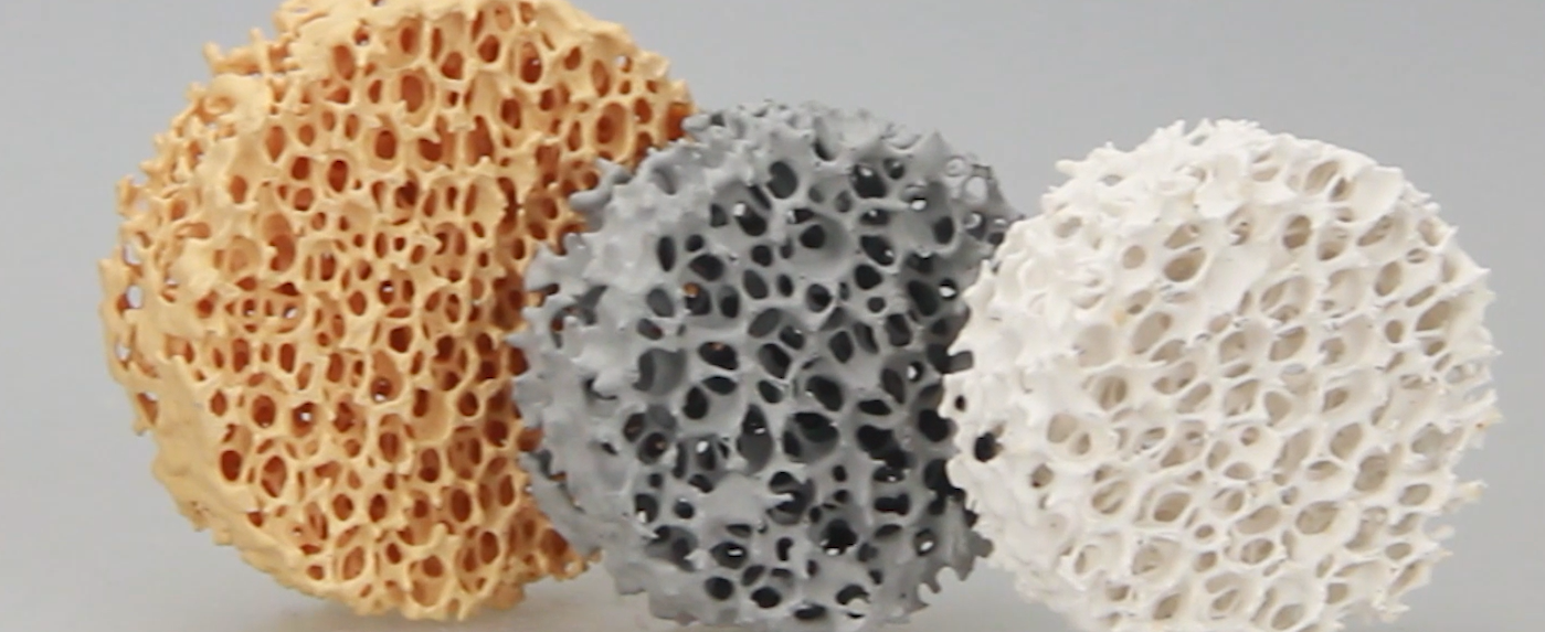
Two filter geometries dominate brass foundry floors, and they’re not interchangeable. Foam ceramic filters are the popular choice for brass work because they handle high temperatures, resist chemical attack, and have a pore structure that doesn’t clog easily under load. Honeycomb Extruded filters serve a narrower use case: low-inclusion melts where throughput matters more than deep purification.
Structure Drives Performance
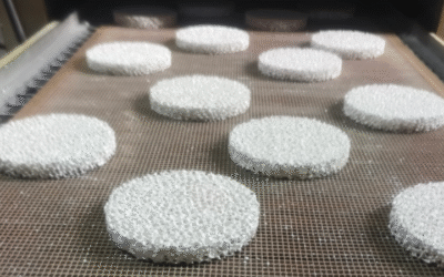
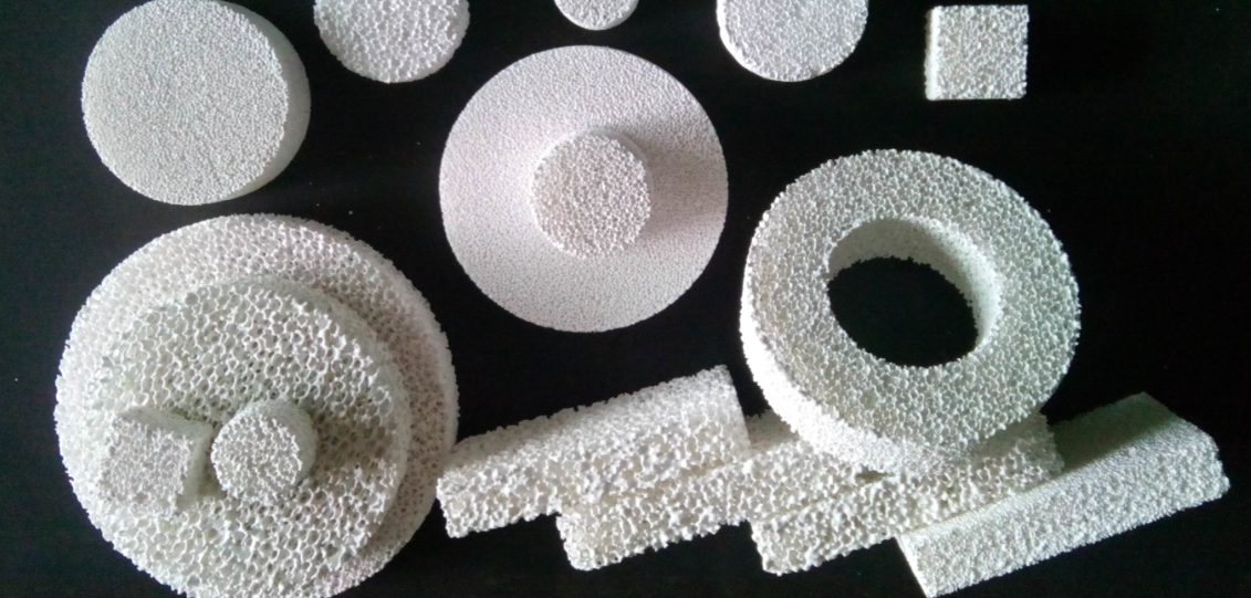
Foam ceramic filters have open porosity of 80%–90%, built as a three-dimensional interconnected network. That tortuous, deep-layer structure puts more surface area in contact with the melt, so it captures microscopic oxide inclusions more effectively. The pore path also straightens flow and cuts turbulence as brass pushes through. Common materials here are Al₂O₃, SiC, and ZrO₂.
honeycomb filters work the opposite way. Straight-through channels mean lower pressure drop and higher flow volume, but that directness limits multi-stage particle capture. Less zigzag means less trapping.
Matching Filter to Brass Chemistry
Zinc-containing brass melts raise a specific concern: wetting and erosion risk against the filter media, plus a need for stable composition retention. porous ceramics stay chemically inert against molten metal, so brass doesn’t aggressively react with the filter body itself. The real risks sit elsewhere:
- Insufficient thermal shock resistance leads to cracking, spalling, and new secondary inclusions from the filter itself
- Pore clogging from oversized inclusion loads drops flow rate mid-pour
- Wetting and erosion happen when the filter media is poorly formulated for sustained high-temperature contact
That’s why alumina, zirconia, and silicon carbide systems get favored. They hold up chemically and thermally where lesser formulations fail.
Quick Comparison
| Type | Brass Suitability | Strength | Main Risk | Best Use Case |
|---|---|---|---|---|
| Foam Ceramic | High | 80–90% porosity, deep filtration, flow straightening | Clogging under heavy inclusion load | Fine oxide removal, surface quality improvement |
| Honeycomb Extruded | Moderate | High throughput, low pressure drop | Weaker fine-particle retention | High-volume, low-inclusion pours |
Bottom Line
For most brass casting operations chasing clean surfaces and fewer oxide inclusions, foam ceramic filters are the default choice. Honeycomb designs earn their spot in coarse, front-end filtration where flow rate matters more than purification depth. Pick based on inclusion load and thermal cycling demands, not habit.
Critical Operating Parameters
Get the numbers wrong here, and the filter cracks before it ever catches an oxide.
Preheat rate decides whether the filter survives first contact with molten brass. Metal sintered filter media typically ramps at 5–10°C/min, holding at target temperatures like 900–1100°C for 2 hours to bleed off thermal stress. Sintering-stage control tightens further: 950–1050°C, ramp capped at ≤2°C/min, hold 1–2h. Skip this, and you get thermal shock cracking. Bellows-style connections and Insulating sleeves absorb the expansion instead of letting the ceramic body take the hit.
Ceramic-specific thermal protocols matter for high-shock pours. A 300–400°C, 2-hour soak cuts residual stress. Thin-wall sections climb at ≤80°C/h below 300°C; thick sections (>15mm) stay under 50°C/h. Above 600°C, ramp can push to 100°C/h. Holding plateaus at 573°C and 870°C for 30 minutes each releases phase-transformation stress. Thermal shock testing on SiC-alumina filter panels backs this up: 50 cycles of 1600°C-to-25°C water quenching produced crack density under 0.3/cm², versus >1.8/cm² on conventional corundum media.
PPI selection follows pour speed and casting wall thickness. Faster pours with heavier melt erosion call for higher pore connectivity and lower resistance. Thinner walls need tighter control over temperature drop and pressure drop to avoid stagnant flow.
Flow control keeps efficiency stable long-term. Sintered filters hold 99.97% initial efficiency across 300–500°C, staying above 98.5% after 1,000 thermal cycles, provided temperature swings stay within ±10°C. A sharp efficiency drop or rising pressure drop signals it’s time to pull the filter.
Real-World Applications of Ceramic Filtration in Brass Foundries
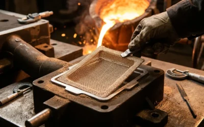
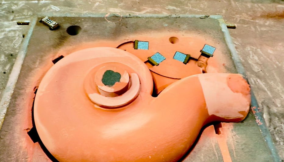
Walk any working brass foundry floor and you’ll find ceramic filters doing quiet, unglamorous work at four specific points: the sprue base, the cross gate, the ingate, or right inside the pour cup. The placement rule that comes up again and again — closer to the mold cavity is better — exists for one reason. It shrinks the window for re-oxidation between filtration and fill.
Material and Thickness Choices for Brass
Cordierite foam ceramic dominates copper-alloy filtration, with mesh sizes typically running 1–1.2 mm. Thickness matters more for brass than people assume. Small aluminum castings often get by with filters ≤15 mm thick. Brass and copper alloys, being denser and more erosive on refractory media, push toward 20–25 mm thick foam panels.
Where This Pays Off: Valves and Precision Hardware
Valve bodies, fittings, and small precision hardware live and die by surface quality and pressure-tightness. This is exactly where oxides and non-metallic inclusions do the most damage — slag inclusions, pinholes, surface pitting, secondary oxidation defects. Ceramic filtration attacks these through the same mechanical interception and flow-straightening principles covered earlier, and the yield gains show up directly on the inspection line.
Sizing the Filter Correctly
Filter working area should run 4–6 times the choke section of the gating system. Undersize it and pressure drop kills fill speed. One rule holds across every brass foundry guide: filters don’t control pour speed. Gating design still targets a fast, complete runner fill to limit turbulence exposure and gas pickup at the filter face.
For operations chasing tighter inclusion control, some setups use 20 μm pore, 8–12 mm thin ceramic membranes positioned right at the gate entrance, catching particles during the high-velocity initial fill. This is a higher-precision benchmark worth evaluating against your own pour temperature, flow rate, and pressure drop — not a universal drop-in replacement.
Continuous Casting vs. Batch Casting: Placement Logic Differs
| Aspect | Continuous Casting | Batch Casting |
|---|---|---|
| Filtration goal | Stable melt quality over long runs | Clean each individual pour |
| Typical position | Ladle outlet, tundish, or front of supply line | Pour cup, sprue base, cross gate, ingate |
| Core priority | Continuous flow, clog resistance, long service life | Proximity to cavity, short-path rectification |
| Main risk | Clogging causes flow decay over time | Filter placed too far allows re-slagging |
For batch-cast brass valve and hardware production, the practical sequence runs pour cup → sprue base → cross gate → ingate, with filters pushed as close to the cavity as geometry allows. Continuous casting setups favor front-end or mid-buffer placement, sometimes with multi-stage filters in series when higher cleanliness is non-negotiable.
Measurable Industry Reference Points
Brass-specific percentages are scarce, but adjacent casting data gives a workable benchmark. Foam ceramic filtration has pushed pass rates to 80% in iron casting and cut non-metallic inclusions by roughly 20% in continuous steel casting. Neither number is brass-exclusive, but both reflect the same underlying effect ceramic filters deliver on molten brass: fewer inclusions, steadier flow, less secondary oxidation, higher acceptance rates.
Four Checks Before Selecting a Filter
- Alloy match: cordierite-based foam, temperature-rated for brass chemistry
- Pore size: start at 1–1.2 mm, tighten up for precision parts
- Placement: near-cavity for batch pours, front-end/stable-flow position for continuous supply
- Area sizing: 4–6x choke section to avoid excessive pressure drop
Conclusion
Ceramic filters remove oxides and inclusions from molten brass through three synchronized mechanisms. Tortuous-path filtration traps particles mechanically. Surface and depth filtration catches contaminants at multiple scales. And turbulence reduction keeps the melt flowing smoothly into the mold. Together, these processes strip away dross, oxide films, and refractory debris that would otherwise weaken castings, cause porosity, or ruin machined surfaces.
For foundries, the payoff is real. Cleaner brass means fewer rejects, better mechanical properties, and castings that hold up under pressure. But filter selection and pore-size matching matter just as much as the technology itself.
If you’re pouring brass and still fighting inclusion defects, don’t guess your way through it. Talk to a filtration specialist. Match your filter type to your alloy and gating system. Then start measuring the difference in your scrap rate. Clean metal isn’t luck. It’s engineering.