Choosing the wrong ceramic foam filter for your iron type isn’t just an efficiency problem — it’s a scrap problem. Ductile Iron and gray iron behave in different ways inside the mold. They solidify at different rates and carry different inclusion loads. The filtration approach that works well for one can damage results for the other. Yet both are often treated as interchangeable in gating design.
This comparison of Ceramic foam filtration for ductile iron vs. Gray Iron breaks down where those differences actually matter — PPI selection, filter-to-gate ratios, pressure drop behavior, and material chemistry. Use it to make filter decisions based on metallurgical reality, not guesswork.
What Makes Ductile Iron and Gray Iron Different (And Why It Changes Everything About Filtration)
The difference starts at the microscopic level. It shapes every filtration decision you’ll make.
In gray iron, graphite grows in flake form. It spreads through the metal matrix like a web of connected cracks. Those flakes act as stress concentrators. The internal structure comes pre-loaded with fracture initiation sites. That’s just the nature of gray iron.
Ductile iron works differently. Magnesium or rare earth additions force the graphite to grow as spherical nodules — isolated, rounded, and contained. The matrix stays continuous. The metal can stretch, absorb impact, and carry tensile load in ways gray iron cannot.
Here’s what that looks like in numbers:
- Tensile strength: Gray iron sits at 100–300 MPa. Ductile iron reaches 400–700 MPa, with high-strength grades pushing past 900 MPa — 1.5 to 3× stronger under the same casting conditions.
- Elongation: Gray iron barely moves before fracture — often under 2%, which is near zero in many grades. Ductile iron stretches 5–20% depending on the matrix. That’s an order of magnitude difference.
- Impact toughness: Gray iron absorbs about 2 ft·lb. Ductile iron starts at 7 ft·lb minimum and often goes much higher.
Gray iron has no defined yield point. The flake graphite triggers micro-crack propagation too fast for a stable yield plateau to form. Ductile iron yields at 276 MPa (40,000 psi) and holds steady.
Why Inclusions Hit Ductile Iron Harder
This is where filtration stakes become unequal.
In gray iron, the flake network already controls failure behavior. An oxide inclusion landing inside that structure adds a small, sharp defect onto a surface already full of sharp defects. The extra damage is real, but limited — the material’s weakness is built in from the start.
In ductile iron, the matrix is continuous. The graphite nodules create controlled, localized stress concentration — and nothing more. That’s the core of its toughness advantage. Drop a hard oxide inclusion or an unfiltered bifilm into that clean matrix, and you’ve created a new, dominant stress concentration point. The material was never designed to handle that.
The consequences are severe and uneven:
| Condition | Gray Iron Performance Drop | Ductile Iron Performance Drop |
|---|---|---|
| Standard inclusion level | Tensile: ~10–20% reduction | Elongation: 40–70% reduction |
| High inclusion load | Localized cracking, machining scrap | Impact toughness collapses toward gray iron levels |
There’s another problem. Oxide bifilms in ductile iron don’t just start cracks — they consume the magnesium responsible for nodule formation. This triggers localized de-nodularization. Graphite reverts toward flake form in contaminated zones. The alloy’s entire mechanical design breaks down from within, with no visible warning on the surface.
That’s why filtration for ductile iron isn’t a process refinement. It’s a metallurgical requirement.
How Ceramic Foam Filters Work: The Depth Filtration Mechanism That Matters for Both Iron Types
The filter sitting in your gating system isn’t doing what most people think it’s doing.
A screen filters by size exclusion — particles too big to pass through get stopped at the surface. That’s a simple, intuitive model. It’s also incomplete. Ceramic foam Filters run on a different principle entirely. That difference explains why they outperform screens on both gray and ductile iron.
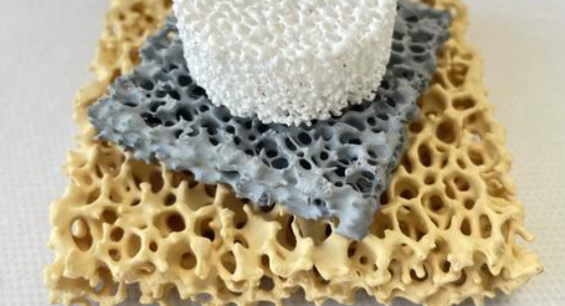
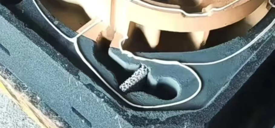
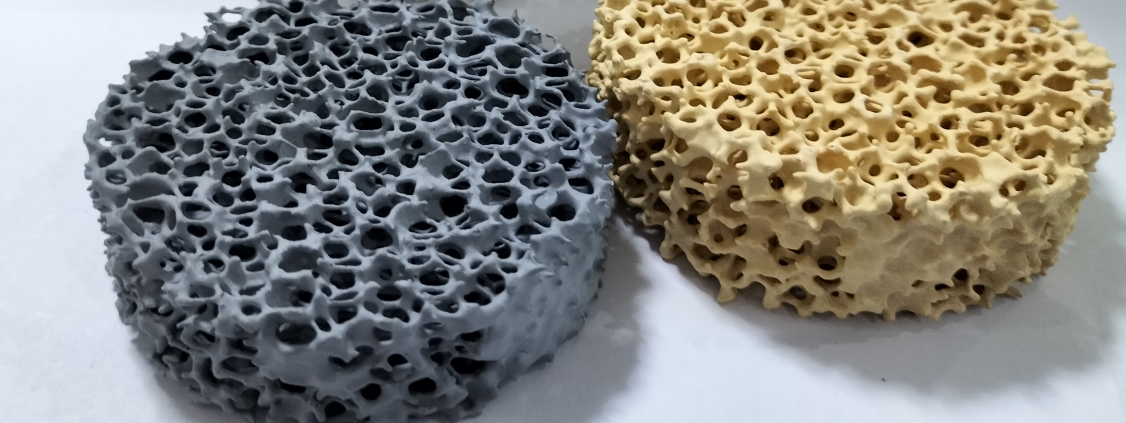
The mechanism is called depth filtration, and the key is structure. A ceramic foam filter isn’t a flat barrier with holes in it. It’s a three-dimensional labyrinth — an interconnected network of open cells and ceramic struts running through the full thickness of the filter, 10–50 mm deep. Metal flowing through that structure doesn’t travel in a straight line. It changes direction dozens to hundreds of times before it exits the other side.
Every directional change is a capture event waiting to happen.
The Three Ways Inclusions Get Trapped
Three distinct mechanisms work together inside that tortuous path:
- Inertial impaction: Dense oxide particles — Al₂O₃, FeO·SiO₂ — have momentum. The flow bends hard around a ceramic strut. The particle can’t follow that curve. It continues forward, strikes the ceramic surface, and sticks. This is the dominant mechanism for particles in the 20–100 μm range.
- Interception: Smaller particles that do follow the streamline still get caught. The flow channel narrows enough that the particle’s own diameter brings it into contact with the wall. No deviation required — proximity does the work.
- Deep-bed adsorption: The finest particles — MgO and MgS reaction products from ductile iron’s magnesium treatment, often just a few microns across — are too small for either mechanism above to dominate. At low flow velocities, micro-scale disturbances and surface energy effects pull them toward rough ceramic surfaces. They adhere and stay. This is why ductile iron depends on depth filtration in ways gray iron doesn’t.
What This Means in Practice
The practical result is a capture range that surface filtration can’t match. A simple screen is limited to particles ≥50–100 μm — anything smaller passes straight through. A ceramic foam filter running in depth-filtration mode can capture inclusions down to 10–20 μm, even at nominal PPI ratings of 10–30.
Removal efficiency varies by inclusion size and filter design:
| Inclusion Type | Typical Particle Size | Removal Efficiency |
|---|---|---|
| Large slag / sand | >100 μm | 80–90% |
| Fine oxides | 10–50 μm | 40–70% |
Thickness matters more than most foundry engineers account for. A 50 mm filter and a 10 mm filter with identical PPI ratings don’t perform the same on fine inclusions. The deeper bed accumulates more capture events across its full thickness. For high-cleanliness ductile iron, 30–40 mm is the standard target. MgO reaction products need that extended contact path to reach acceptable removal rates. A shallower filter simply doesn’t give them enough time in the bed.
Pressure drop behavior also separates depth filtration from surface screening. A screen builds a filter cake at the entry face — pressure rises fast, flow rate drops, and fine inclusions begin to punch through. A foam filter spreads its inclusion load through the entire volume. Pressure builds at a steadier pace. Flow time extends. The system handles higher metal throughput before performance degrades. That’s why filter area in engineered gating systems is sized at 2–4× the choke cross-section — not to cut flow resistance at the start, but to sustain filtration quality through the full pour.
PPI Selection: Why Ductile Iron Needs Coarser Foam Than You’d Expect
Here’s the surprising truth about ductile iron filtration: the metal that needs the cleanest result requires the coarsest foam to achieve it.
Standard ceramic foam filters — the rare earth SiC type most foundries stock — come in five common grades: 10, 15, 20, 25, and 30 PPI. For gray iron, 10 through 20 PPI are all solid choices depending on the casting. For ductile iron, the recommended range tightens to 10–15 PPI. That ceiling isn’t cautious — it’s driven by load limits.
The Load Numbers That Explain Everything
Here’s the hard limit that governs PPI selection for ductile iron:
- Ductile iron: maximum metal load of ≤ 2 kg/cm² of filter area
- Gray iron: maximum metal load of ≤ 4 kg/cm² of filter area
That 2:1 ratio has a clear reason behind it. Magnesium and rare earth treatment creates spheroidal graphite and gives ductile iron its strength. That same chemistry also produces a heavy load of oxides, sulfides, and complex reaction slags. All of it enters the Gating System. The inclusion load runs about double what gray iron generates.
Finer PPI grades (20–30) have smaller individual pores. In clean metal with a light slag burden, that works fine. In ductile iron, it sets up a cascade failure.
What Early Clogging Looks Like
Take a 20 kg ductile iron casting poured through a filter with 10 cm² of face area. At the 2 kg/cm² limit, you’re right at the edge. Now use a 20–30 PPI filter instead of the recommended 10–15:
- Magnesium reaction products start blocking the smaller pores within the first seconds of the pour
- Effective flow area drops from 10 cm² down to 5–6 cm²
- The real load climbs to 3.3–4.0 kg/cm² — well into gray iron territory and far beyond ductile iron limits
- Metal velocity rises in the remaining channels. Temperature at the flow front drops. Thin-walled sections stop filling.
The result: misruns and cold shuts in the back half of the pour, residual slag piled in the runner, and a scrap report that blames gating design — not the filter grade that caused the problem.
Wall Thickness and Pour Temperature Change the Specific Number
Within the 10–15 PPI window, where you land depends on two casting variables:
| Casting Condition | Recommended PPI | Load Target |
|---|---|---|
| Thin-wall (≤5–8 mm), moderate temperature | 10 PPI | ≤ 1.5 kg/cm² |
| Mid-wall, normal pour temperature | 10–15 PPI | ≤ 2.0 kg/cm² |
| Heavy-wall (≥20 mm), higher superheat, good slag control | 15 PPI max | ≤ 2.0 kg/cm² |
Thin-wall castings are sensitive to temperature. A finer filter adds pressure drop. That means a slower fill, faster heat loss, and a race the metal often loses. For thin-wall work, 10 PPI is the default — not a backup option.
Higher pour temperatures boost fluidity but also raise reaction slag volume. That tradeoff still keeps the PPI ceiling at 15. A heavy slag burden calls for better upstream slag control — ladle standing time, baffle design — not a finer filter at the end of the line.
Filter thickness plays a role too. Pair the coarser PPI with enough bed depth — ≥25 mm for most ductile iron applications. The longer contact path makes up for the larger cell openings. Coarser isn’t weaker. It’s the right match for the metal you’re pouring.
Filter-to-Gate Area Ratio: The Critical Design Parameter Most Foundries Underestimate
Most foundries get the filter grade right — then undermine it with an undersized filter area. The ratio between filter face area and choke cross-section is not a secondary consideration. It determines whether your filtration system controls the flow or becomes the problem.
The baseline numbers are simple. Gray iron needs a filter face area of at least 2× the choke area. Ductile iron needs 3× minimum. In practice, the safer working target is ≥5:1. That keeps fill stable and pressure drop low throughout the pour.
Why the Ratio Hits Ductile Iron So Much Harder
There’s a threshold effect in ductile iron gating systems. Drop the filter-to-choke ratio K below 4, and the filter stops acting as a passive cleaner. It starts behaving like a choke restriction instead. Flow rate falls. Fill time stretches. The metal cools faster than the design intended. Push K above 6, and control shifts back where it belongs — to the runner system, not the filter.
That window — 4 to 6 — is the target range for ductile iron gating. Gray iron tolerates a tighter ratio. Ductile iron does not.
The loading data makes this clear. Run a 100 kg casting through both materials at their design limits:
| Material | Design Loading | Required Filter Area |
|---|---|---|
| Gray iron | 4 kg/cm² | 25 cm² |
| Ductile iron | 2 kg/cm² | 50 cm² |
Same casting weight. Double the filter area. That’s not a design preference. It’s the direct result of different inclusion loads and different pressure-drop tolerances.
One detail most gating layouts get wrong: size the filter from the actual face area, not the nominal filter dimensions. Also, the exit face needs ~30% support area to hold up under metallostatic pressure. Skip that, and filter fracture becomes a real risk before the mold fills.
Flowability, Pressure Drop, and the Risk of Incomplete Filling in Ductile Iron
Ductile iron leaves almost no room for error at the flow front — and the numbers prove it.
Mold-filling simulations validated against physical trials use a metric called cast liquid fraction (CLF) to define when flow becomes unreliable. For gray iron GJL-250, the lower CLF threshold sits at 60%. The metal can still travel through semi-solid conditions and fill the cavity. For ductile iron GJS-400-15, that lower threshold drops to 10%. Once the liquid fraction at the flow front falls below that point, the fill stops — regardless of what’s left in the sprue.
That 50-point gap is the core of the flowability problem.
The Pressure Drop Chain That Creates Scrap
Every source of resistance in your gating system adds to ΔP_flow. Tight runners, sharp bends, undersized filters, long thin ingates — all of it stacks up. For a sound ductile iron casting, this inequality has to hold:
P_riser + P_exp + P_applied > P_sh + P_atm + ΔP_flow
Too much ΔP_flow and the right side wins. Metal slows down. The flow front cools. Liquid fraction drops below that 10% threshold. You get misruns, cold shuts, and underfill. On top of that, 50% of Shrinkage defects in ductile iron trace back to gating and feeding resistance — not metallurgy.
Gray iron, with its 60% CLF floor, handles longer semi-solid flow. Its practical flow length runs 20–40% greater than ductile iron under identical section thickness and temperature conditions. Ductile iron in unpressurized thin sections starts showing misrun rates above 20–30% once wall thickness drops below 3 mm without a compensating gating design.
What to Do About It
These are the specific fixes that work:
- Keep pouring temperature at 1350–1420 °C, controlled within ±10 °C. A 20–30 °C drop below target raises misrun frequency in thin-section runs — the effect shows up fast and clearly in scrap data.
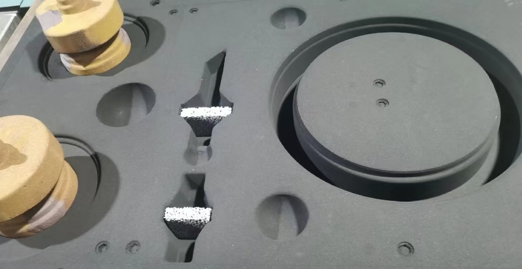
- Place filters near the sprue-runner junction — that’s where metal is hottest and head pressure is highest. Downstream thin sections then avoid absorbing the full ΔP_flow penalty.
- Add more ingates rather than enlarging each one. Filling time scales with n⁻¹/², so doubling the ingate count cuts filling time by ~29%. You reduce misrun risk without adding turbulence.
- Increase sprue height to build hydrostatic head. This offsets filter and runner pressure losses.
Keep fine filters away from positions right before multiple thin ingates. At that junction, pressure drop stacks up and available head is minimal. The result is cold shuts where converging flow fronts meet below temperature — a consistent source of scrap.
Material Selection for the Filter Itself: SiC vs Al₂O₃/C for Each Iron Type
The temperature numbers settle this debate on their own.
Gray iron and ductile iron both pour in the 1350–1480°C range. Alumina (Al₂O₃) Foam filters top out at around 1100°C continuous service. That’s a gap of 150–280°C. This isn’t a margin of error — it’s the point where alumina softens, deforms, and breaks apart. Hard ceramic fragments drop straight into the melt. Those fragments don’t dissolve. They turn into inclusion defects. They ruin castings and eat tooling.
SiC filters don’t have this problem. Their practical ceiling in foundry use reaches 1500°C — well above any iron pouring temperature you’ll see in production. The US iron foundry industry standardized on SiC ceramic foam for this reason. It’s not a preference. SiC is the one material that survives the thermal shock of iron contact, pour after pour, without breaking down.
Why SiC Holds Up and Al₂O₃ Doesn’t
Two physical properties explain it.
First, coefficient of thermal expansion. SiC sits at ≈4.5 × 10⁻⁶/°C. Al₂O₃ runs almost double that at ≈8.0 × 10⁻⁶/°C. Hot iron hits the filter face and that expansion gap drives internal stress. The lower the CTE, the smaller that stress spike. SiC holds its structure. Al₂O₃ cracks.
Second, SiC’s high thermal conductivity spreads heat across the filter body faster. A smaller temperature gradient means less thermal shock. Both properties push in the same direction.
Side-by-side casting trials back this up. Under the same iron casting conditions, alumina filters crack and collapse. sic filters stay intact.
The Ductile Iron Wrinkle: Phosphate-Free Binders
For gray iron, standard SiC foam filters work with no special requirements. Ductile iron adds one more condition.
Magnesium treatment sets ductile iron apart from gray iron. It’s the chemistry behind spheroidal graphite — and behind every mechanical advantage ductile iron offers. Phosphorus reacts badly with magnesium. It degrades nodularity. It breaks down the entire metallurgical design you’re relying on.
So SiC filters for ductile iron use phosphate-free binders as a standard production requirement. This isn’t optional. A filter that introduces phosphorus into a magnesium-treated melt attacks the alloy’s core chemistry at the exact moment of pouring.
The selection rule is straightforward:
- Gray iron → SiC foam, 10–20 PPI, standard binder
- Ductile iron → SiC foam, 20–30 PPI, phosphate-free binder — check the datasheet and confirm this; don’t assume
- Compacted graphite / high-Si irons → same filter requirements as ductile iron
One more check for ductile iron: confirm the filter datasheet states chemical inertness to Mg-treated melts. MgO-rich slags from the nodularizing reaction create localized chemical attack at the filter surface. SiC resists those slags. Al₂O₃-only foams fail on both counts — they can’t handle the temperature, and they can’t handle the chemistry.
For steel castings above 1600°C, SiC degrades and reacts with iron. At that point, Zirconia (ZrO₂) Filters are the correct step up. But for every iron grade from standard gray to high-strength ductile, SiC is the default and the ceiling. The one reason to look past it is if you’re working with specialized Al₂O₃–SiC–C composite filter bodies rated for iron temperatures — a narrow case, not standard practice.
Side-by-Side Comparison: Key Filtration Parameters at a Glance
The numbers say it better than any explanation. Here’s how ductile iron and gray iron compare across every filtration parameter that matters in production.
| Parameter | Gray Iron | Ductile Iron |
|---|---|---|
| PPI Range | 10–20 PPI | 20–30 PPI |
| Filter-to-Choke Ratio | ≥4 (thin-wall: 6–8) | ≥4 (critical parts: 6–10) |
| Inclusion Sensitivity | Medium | High |
| Critical Inclusion Size | >30–50 μm | 5–50 μm |
| Filter Material | SiC or high-strength cordierite | SiC, phosphate-free binder |
| Max Metal Load | ~4 kg/cm² | ~2 kg/cm² |
A few things stand out right away.
First, the PPI gap. Gray iron works at 10–20 PPI. Ductile iron needs 20–30 PPI — a full range step finer. That’s because the 5–20 μm inclusion zone is where its mechanical properties start to fail. Moving from 20 to 30 PPI improves fine inclusion removal by 12–15 percentage points. That gap separates a sound fatigue-critical casting from a warranty return.
Second, the inclusion size target is different. Gray iron’s surface quality and machinability problems come from particles above 30–50 μm. Ductile iron is another story. Its tensile strength, fatigue life, and impact toughness all depend on what happens in the 5–50 μm band. Coarser filters don’t reach that range at all.
Third, each PPI step up has a real cost. Flow capacity drops 35–45% per PPI grade increase. Going from 20 to 30 PPI without expanding the filter area adds pressure drop. Worse, it can push the metal load past the 2 kg/cm² limit and starve thin sections of fill.
Use this sizing formula to stay on track:
Required filter area (cm²) = Metal flow rate (kg/min) ÷ Max specific flow rate (kg/min·cm²)
Add ≥20% safety margin on top.
For high-performance ductile iron parts — automotive suspension, steering knuckles, crankshafts — go with 30 PPI, a filter-to-choke ratio of 6–10, and SiC foam with a phosphate-free binder. Gray iron general castings work well at 10–20 PPI, ratio ≥4. These are not interchangeable starting points. Each one is a direct response to two materials that behave in fundamentally different ways.
Practical Decision Guide: How to Choose the Right Ceramic Foam Filter for Your Specific Casting
Filter selection isn’t a catalog exercise. It’s five decisions made in sequence. Each one narrows the spec until the right filter for your casting becomes clear.
Work through the steps in order. Skip one and the numbers fall apart.
Step 1: Lock In Your Iron Type First
Everything else flows from this.
Gray iron tolerates finer filtration. Inclusion loads are lower, fluidity is higher, and the material forgives small errors in gating design. Standard range: 10–20 PPI. For high surface quality requirements, you can push to 20–30 PPI.
Ductile iron is less forgiving in every direction. The inclusion load is higher, fluidity is worse, and clogging happens faster. Default to coarser pores: 10–15 PPI. For a dirty melt, go straight to 10 PPI. Push toward 20 PPI only if your upstream slag control is tight and your process stability is well-documented.
Step 2: Calculate Required Filter Area From Casting Weight
This is where most foundries undersize their filters.
The metal load limits are firm:
| Iron Type | Load Limit | Example: 24 kg Casting |
|---|---|---|
| Gray iron | 4–6 kg/cm² | Filter area: ~4–6 cm² |
| Ductile iron | 2–4 kg/cm² | Filter area: ~6–12 cm² |
Same casting weight. Double the filter area. That’s not being cautious — that’s the direct result of different inclusion chemistry.
For large castings above 1,000 kg, a single filter won’t hold. Use multi-section foam filter arrays — Al₂O₃/carbon or ZrO₂ bodies for extreme mass — staged across the gating system.
Step 3: Adjust PPI Based on Wall Thickness and Complexity
Thick walls give you room to work. Thin walls do not.
- Thick-wall, simple geometry: Focus on flow capacity and clog resistance. Gray iron: 10–15 PPI. Ductile iron: 10 PPI is the safe default.
- Thin-wall, complex runners, tight surface quality: Gray iron can run 20 PPI, with high-end applications reaching 30 PPI. Ductile iron at 15–20 PPI works only with a very clean melt and enough metal head to handle the added pressure drop. Don’t assume — verify.
Step 4: Match Pore Size to Pouring Temperature
High viscosity, low fluidity, or large inclusions → coarser pores, lower PPI.
Low viscosity, high fluidity, fine inclusions → finer pores, higher PPI.
Typical temperature ranges for reference:
- Gray iron pours at 1350–1450°C
- Ductile iron pours at 1380–1500°C
Higher pour temperature improves fluidity and supports a modest PPI increase. Lower pour temperature takes that option off the table. For gray iron below target temperature, don’t exceed 20 PPI. For ductile iron running cool, hold at 10–15 PPI — no exceptions. Low head pressure combined with fine pores creates cold shuts faster than any other single variable.
Step 5: Size the Filter Against Your Gating Choke Area
The filter-to-choke ratio decides whether the filter controls flow or fights it.
- Gray iron: filter face area ≥ 2× the choke cross-section. Best practice targets 4–6× choke area.
- Ductile iron: ≥ 3× choke cross-section minimum. Design target: 4–6× choke area to keep flow smooth and continuous.
- Gray iron minimum head before the filter: ≥200 mm.
For large or high-cleanliness castings, consider two-stage filtration. A coarse pre-filter (low PPI) sits upstream to catch bulk slag. A fine filter (higher PPI) sits downstream for precision cleaning. This setup handles heavy inclusion loads without triggering the clog-cascade that kills single-filter designs.
The Mistakes That Keep Showing Up
Three errors cause a disproportionate share of filtration-related scrap.
Using gray iron PPI specs on ductile iron. Running 20–30 PPI on ductile iron pushes the filter past its clog threshold within seconds of the pour. Pressure drop spikes. Flow rate drops. Thin sections go cold. The fix: drop to 10–15 PPI and recalculate filter area at 2–4 kg/cm².
Applying gray iron area sizing to ductile iron. Designing at 4–6 kg/cm² for ductile iron starves flow and risks mechanical filter failure under high head pressure. For the same casting weight, ductile iron needs 50–100% more filter area than gray iron. Get there by upsizing the filter, adding a second one, or both.
Using a 2× choke ratio for ductile iron. A filter area of just 2× the choke creates turbulence downstream in ductile iron systems. Secondary oxidation rises. Slag entrainment follows. Start at 3× minimum. Target 4–6× in practice.
Conclusion
Ductile iron and gray iron are not interchangeable. Treating them the same way is how scrap rates climb and yields drop.
The basics are clear. Ductile iron needs coarser PPI ratings, higher filter-to-gate ratios, and SiC filters built to handle the thermal stress of magnesium-treated melts. Gray iron works differently. It performs better with tighter pore structures and handles Al₂O₃/C chemistry without issues. Get the pairing wrong, and no gating system adjustment will fix the results.
Ceramic foam filtration for ductile iron vs. gray iron is not a matter of preference. It comes down to metallurgical physics.
So here’s your next step: bring the side-by-side parameters from this guide into your next tooling review. Match your filter spec to your iron chemistry. Don’t let purchasing habits drive that decision.
The gap between a good casting and a scrapped one often comes down to a single filter — the right one, chosen for the right iron.