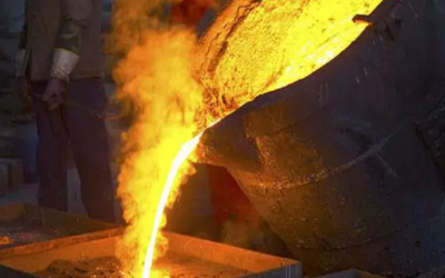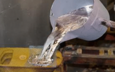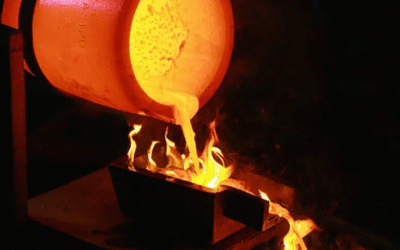
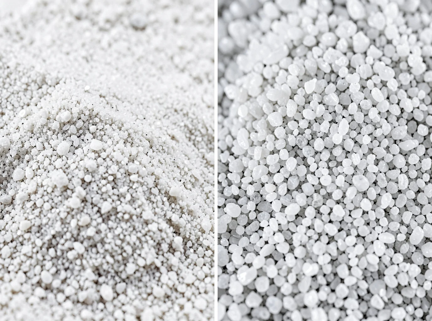
That scrap casting sitting on your shop floor with the unexplained gas porosity might have nothing to do with your melt chemistry. More often than engineers want to admit, the real culprit sits in the molding sand hopper.
Foundry sand is far from an off-the-shelf commodity. Silica, zircon, chromite, olivine, resin-bonded—each behaves differently under thermal shock, handles permeability and grain fineness on its own terms, and will either save your pour or ruin it. Green Sand casting works well for Gray Iron, but turns into a liability the moment you pour reactive alloys or thin-wall steel sections.
This breakdown walks through what separates these five sand types across thermal resistance, dimensional stability, cost per pound, and reclamation rates, so you can match the right sand to the right casting before defects start piling up.
Silica Sand: The Industry-Standard Baseline
Ninety percent of foundries reach for silica sand without a second thought, and the chemistry explains why. SiO₂ content runs 94–98% for iron and non-ferrous work, climbing past 98% when steel casting demands tighter refractory margins. Pure quartz melts at 1,760°C, but real-world foundry sand carries traces of Al₂O₃, Fe₂O₃, CaO, and alkali oxides that drag down the usable softening point. Most engineering specs set the floor at 1,690–1,710°C for high-refractory grades. True particle density sits near 2.65 g/cm³, while bulk density in the mold runs 1.4–1.6 g/cm³.
Silica fails at 573°C, when alpha-quartz flips to beta-quartz and the grains expand rapidly. This phase change drives rat-tails, scabbing, and veining defects in sand casting far more than the melting point does. While reference tables often list linear expansion around 0.45%, actual peaks vary by mineral deposit. Check the expansion curve for your specific sand lot rather than relying on a general spec sheet.
Grain Size and Permeability Tradeoffs
Coarse grains create open pore channels that boost mold permeability, letting steam and decomposition gases vent before they cause pinholes. That permeability comes at the expense of surface finish and raises the risk of metal penetration. Fine grains improve surface detail but restrict gas venting, and they require extra clay and water to reach target bond strength, introducing even more gas into the mold.
Most general-purpose iron and aluminum green sand casting operations settle on AFS GFN 50–60. Thin-wall or detailed parts skew finer, while heavy castings require coarser sand. Typical green sand mixes contain 85–90% silica sand, 7–10% bentonite, and 2–5% water. Foundries blend coal dust into iron mixes, but omit it for aluminum to avoid gas pickup and melt contamination.
Zircon Sand: Precision and Dimensional Stability
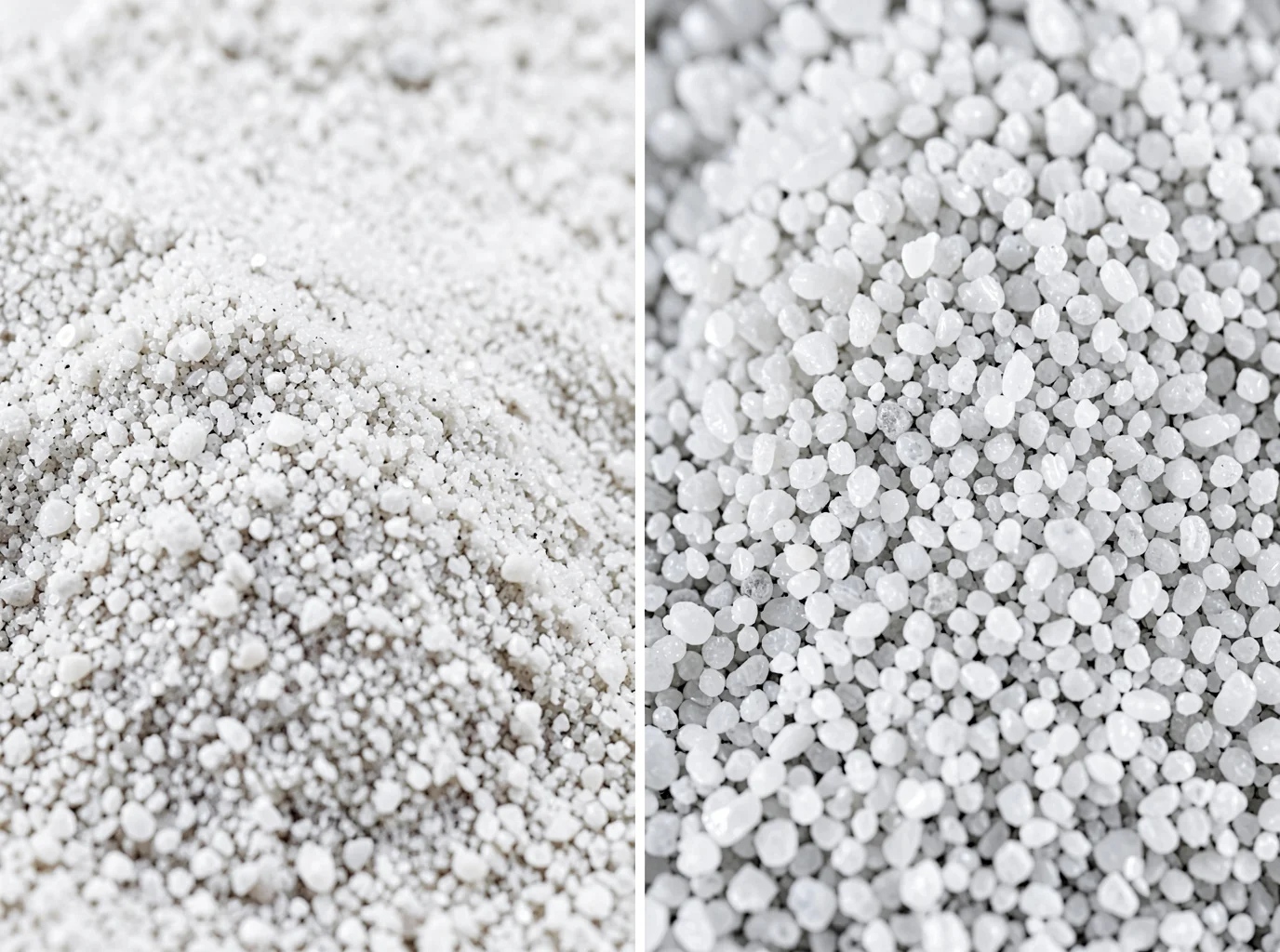
Zirconium silicate (ZrSiO₄) sits in a category of its own. Bulk density runs 2.64–2.80 g/cm³, but true particle density reaches 4.6–4.7 g/cm³, nearly double the weight of silica sand at the same volume. That density difference changes how you calculate mold weight and metal-to-sand ratios on the shop floor.
Melting point claims vary by source. Commercial mineral data cites 2,100–2,300°C, while some high-purity lab tests push past 2,500°C. For practical engineering decisions, 2,180°C works as a reliable design baseline, though you should confirm your supplier’s test method. The advantage comes from thermal expansion: zircon’s linear expansion coefficient sits around 4.5×10⁻⁶/°C, a fraction of silica’s rate. This low expansion prevents veining and dimensional drift during high-temperature pours.
Where Facing Thickness Actually Matters
Foundries seldom fill entire molds with zircon sand because the cost does not justify it. Instead, they apply it as a facing layer over cheaper backing sand:
-
3–6 mm for carbon steel and mid-sized critical surfaces
-
6–10 mm for thick-wall sections, gate areas, and high-erosion zones near pouring points
Investment casting shells offer a useful reference point. They run 8mm overall and increase to 10–12mm for thick-section castings, with zircon placed closest to the metal.
Chemical composition matters too. ZrO₂+HfO₂ content should run 65–66% or higher. Lower grades carry more impurities and fines that undermine sand mold permeability and sintering resistance.
Process Control That Protects the Investment
Zircon’s low wettability with molten metal and high thermal conductivity lower metal penetration risk. Three process variables determine whether you capture that benefit:
-
Narrow grain distribution with minimal dust content stabilizes permeability
-
Thorough drying before pouring, since moisture in zircon facing causes gas porosity and metal spatter
-
Even compaction, because over-ramming blocks gas venting paths
Skip any of these, and you pay premium prices for silica-grade results.
Cost Reality: $800–1,200 Per Ton
That price tag rules out full-mold replacement for most shops. Foundries concentrate zircon sand on specific zones:
High-value placement: – Metal-contact cavity surfaces requiring tight tolerance – necks exposed to erosion – Thick sections and hot spots with extended solidification time – Pump housings, valve bodies, and impellers, where cleanup time costs more than the sand – Stainless, high-manganese, and high-alloy steel castings – Sealing and mating surfaces with limited machining allowance
Skip it on:
– Non-functional exterior surfaces
– Bulk fill zones away from pour impact
– Areas scheduled for heavy machining anyway
– Standard iron castings with low defect sensitivity
Calculate the scrap rate and cleanup labor saved alongside the sand price per ton. That is where zircon earns its cost back.
Chromite Sand: Maximum Thermal Resistance for Heavy Steel Castings
Big steel castings punish sand harder than iron or aluminum ever will. Chromite sand, made from the spinel mineral FeCr₂O₄, exists to take that punishment. Foundry-grade chromite keeps tight impurity limits, capping phosphorus and carbon at 0.003% each. Mineral data sheets cite 2,550°C for pure lab spinel, but the commercial sand in your hopper delivers a refractory range of 1,800–2,150°C, with sintering resistance up to 2,180°C. Steel pours above 1,500°C, so chromite’s working margin stays comfortable even on your worst day.
How It Stacks Up Against Silica and Zircon
|
Property |
Silica |
Chromite |
Zircon |
|---|---|---|---|
|
Thermal expansion |
High, drives veining |
Lower, stable at thick sections |
Very low, best for critical surfaces |
|
Metal penetration risk |
High on large steel castings |
Low: dense, low-wetting, fast cooling |
Low, premium surface protection |
|
Thermal cracking |
High due to quartz inversion |
Low, resists thermal shock |
Low, but costly |
|
Scabbing/sintering |
Prone to burn-on |
High refractoriness limits sticking |
Excellent, reserved for key faces |
|
Thermal conductivity |
Low |
High, speeds solidification |
High |
Furan Resin Compatibility
Acid-cured furan systems work fine with chromite, but watch the acid demand value (ADV). Alkaline contamination in the sand eats your catalyst before it cures the resin, stretching strip times and weakening core strength. Test incoming sand for pH, ADV, moisture, and grain distribution before you recalibrate catalyst ratios. Never reuse a silica-based resin formula without testing first.
Where It Earns Its Keep
Chromite fits large valve bodies, pump housings, turbine casings, gearbox shells, rolling mill components, and chrome-nickel or manganese steel castings with thick sections and hot spots. Most shops apply it as facing or core sand over silica backing, concentrating the material where metal penetration and burn-on happen.
At $200–400 per ton, chromite runs four to eight times the price of silica but a fraction of zircon. It pays for itself through reduced cleanup labor and lower scrap rates on high-value steel parts.
Olivine Sand: The Silica-Free Alternative for Reactive Metals
Manganese steel wrecks silica sand. The MnO in the melt reacts with SiO₂, fuses to the mold wall, and leaves you chiseling burn-on off every casting. Olivine sand sidesteps that fight.
Olivine is magnesium-iron orthosilicate, (Mg,Fe)₂SiO₄, containing about 48% MgO, 41% SiO₂, and 8% Fe₂O₃. Because the silicate is locked directly into the crystal lattice, olivine skips the 573°C phase inversion that makes silica expand suddenly. Foundries source it at 50–60 AFS grain size.
Stable Expansion, Better Cooling
Maximum expansion up to 1,100°C runs around 1.2%, settling to residual expansion of 0.3–0.4%. Some tested samples peak near 1%. Either way, that curve stays far more uniform than silica’s. Less mold movement means less veining, less scabbing, and fewer chill inserts needed to offset a shifting mold wall. Olivine also carries higher density and thermal conductivity than silica, pulling heat out of the casting faster and helping refine grain structure.
Binder Compatibility: Watch the pH
Olivine runs alkaline, with a pH near 9.97. That ruins acid-catalyzed furan and phenolic no-bake systems, because Mg²⁺ and Fe²⁺ ions neutralize acid hardeners before they cure. Bentonite green sand, sodium silicate, and isocyanate-hardened alkyd systems work far better. Never transfer silica catalyst ratios without running bench-life and strip-time trials first.
Where to Deploy It
Crusher jaws, mill liners, rail crossings, excavator buckets—anywhere manganese steel takes abuse. Treat the ~1,400°C fusion point as a hard boundary, and track Fe₂O₃ content to avoid slag formation.
Resin-Coated Sand: Engineering Complex Geometries and Tight Tolerances
Precision parts don’t forgive loose sand. Pump impellers, valve bodies, and thin-wall automotive components need dimensional control that green sand cannot deliver, and that is where resin-bonded sand takes over.
Two resin systems dominate the shop floor. Shell and shell-core molding coats sand grains with phenolic resin, then cures them on a heated pattern running at 230–315°C. The shell hardens in seconds, locking in rigid, repeatable geometry. No-bake cores (furan resin or ester-cured phenolic-urethane) set at room temperature instead, making them a better fit for large or complex internal cavities where heated tooling is impractical.
Where the Tolerance Gains Actually Show Up
|
Process |
Dimensional Accuracy |
Surface Roughness |
Complex Geometry Capability |
|---|---|---|---|
|
Shell/shell-core |
ISO CT7–CT9 |
Ra 2.5–6.3 μm |
Thin walls, deep cavities, fine bosses |
|
No-bake resin sand |
CT8–CT10 |
Ra 12.5–25 μm |
Large, low-volume, complex cores |
|
Green sand |
CT11–CT13 |
Ra 50–100 μm |
Simple shapes, cost-sensitive parts |
Switching from green sand to resin systems moves tolerance from CT11–13 to CT8–10, cuts surface roughness from Ra 50–100 μm to Ra 12.5–25 μm, and drops minimum castable wall thickness from 6–8 mm to 3–5 mm. Shell molding alone often hits linear accuracy near 0.005 mm/mm with draft angles as low as 0.25–0.5°.
Resin Loading Is a Balancing Act
More resin raises strength but drives up gas evolution and reclamation load. The engineering target is the lowest resin content that still survives stripping and handling. Coating uniformity across grains matters more than raw resin volume. On shell cores, overheating cures the outer layer while trapping volatiles inside, so heating time must match core wall thickness.
Quality Factors That Determine Your Sand Selection
Permeability and refractoriness decide whether your casting ships clean or ends up as scrap. Variables like grain shape, binder ratio, and compaction all feed directly into those two results.
Permeability: The Narrow Window Between Two Failure Modes
When sand packs too tight, gas cannot escape. Fine sand fractions, heavy compaction, high moisture, or excess binder choke the mold’s venting capacity. That gas stays trapped, leaving pinholes, blowholes, gas porosity, and sand inclusions. Fine sand yields a smoother finish, but you trade that appearance for higher scrap risk on every pour.
Pack sand too loose, and you face the opposite problem. Coarse grains, wide particle distributions, or weak compaction leave voids where molten metal pushes between grains. That causes mechanical penetration: rough, sintered surfaces that normal shot blasting cannot clean up.
Most foundry sand falls between 0.10 and 0.80 mm, averaging 0.20 to 0.45 mm. Coarse grains vent gas well and require less resin, but the casting finish suffers. Fine grains produce smooth surfaces while driving up binder consumption and gas generation. Mid-range grain sizes split the difference for standard production.
Grain shape matters just as much. Highly spherical, rounded grains flow and pack well with minimal binder, but they do not lock together firmly, which undercuts mold strength. Angular grains lock tightly to build stronger molds, but their greater surface area demands more binder and can restrict permeability. Sub-angular grains provide the most dependable middle ground.
Check grain sizing against AFS 1105-12-S, ASTM C136, or ISO 3310-1, and evaluate particle shape with AFS 1101-13-S. Track your AFS grain fineness number alongside permeability, moisture, compaction, and binder additions. Adjusting one variable on its own usually pushes defects into another area.
Refractoriness: Where Sand Meets Its Thermal Limit
When sand exceeds its refractory limit, the grains or binder melt and fuse to the casting surface. You get glassy or sintered patches, stubborn sand crusts that resist shot blasting, and defects concentrated near gates, hot spots, sharp corners, and soft compaction pockets. Coarse sand and loose compaction accelerate this metal penetration.
Refractory thresholds depend on the base mineral:
-
Silica sand: roughly 1,400°C in lower-purity grades. It handles iron and non-ferrous alloys, but breaks down under high-alloy steel.
-
Chromite sand: around 1,850°C.
-
Zircon sand: around 2,600°C, suited for high-temperature steels and severe hot spots.
Chilling vs. Insulating: Matching Thermal Behavior to Solidification
|
Sand Type |
Thermal Behavior |
Effect on Solidification |
Best Use |
|---|---|---|---|
|
Zircon |
High conductivity, low expansion, low heat capacity; melts ~2,600°C |
Pulls heat fast, creates a sharp cooling zone, refines grain structure |
Hot spots, thick walls, high-temp steel |
|
Chromite |
High conductivity, high density; melts ~1,850°C |
Strong chilling action, speeds local solidification |
Steel castings, thick sections, shrinkage-prone zones |
|
Olivine |
More insulating, higher heat capacity, slower conduction; low expansion |
Cools gradually, mild solidification gradient |
Dimensional stability, low thermal shock zones |
Zircon and chromite act as chilling aggregates, whereas olivine insulates. Zircon carries a specific gravity near 4.6 and extracts heat at roughly twice the rate of silica sand. Chromite follows closely with a 4.5 specific gravity, pairing high bulk density with fast heat conduction for comparable chilling performance.
If you substitute either material for metal chills, recheck your feeding distance, solidification sequence, and hot-spot locations. Ensure the thermal center still freezes last, check sections for localized chill cracks or hard spots, and monitor the thermal gradient where chilling sand meets standard silica or olivine backing sand.
Prevention Checklist
-
Route steel, high-alloy pours, and hot-spot sections to zircon or chromite sand
-
Lower coarse-grain ratios and tighten compaction to seal off metal penetration paths
-
Apply refractory washes on cores and molds around sharp corners, tight fillets, gates, and thermal junctions
-
Control pour superheat, fill time, and compaction consistency across the mold
-
Calcine olivine sand to drive off hydrous serpentine and cut down on pinholes
How to Choose the Right Foundry Sand for Your Casting Project
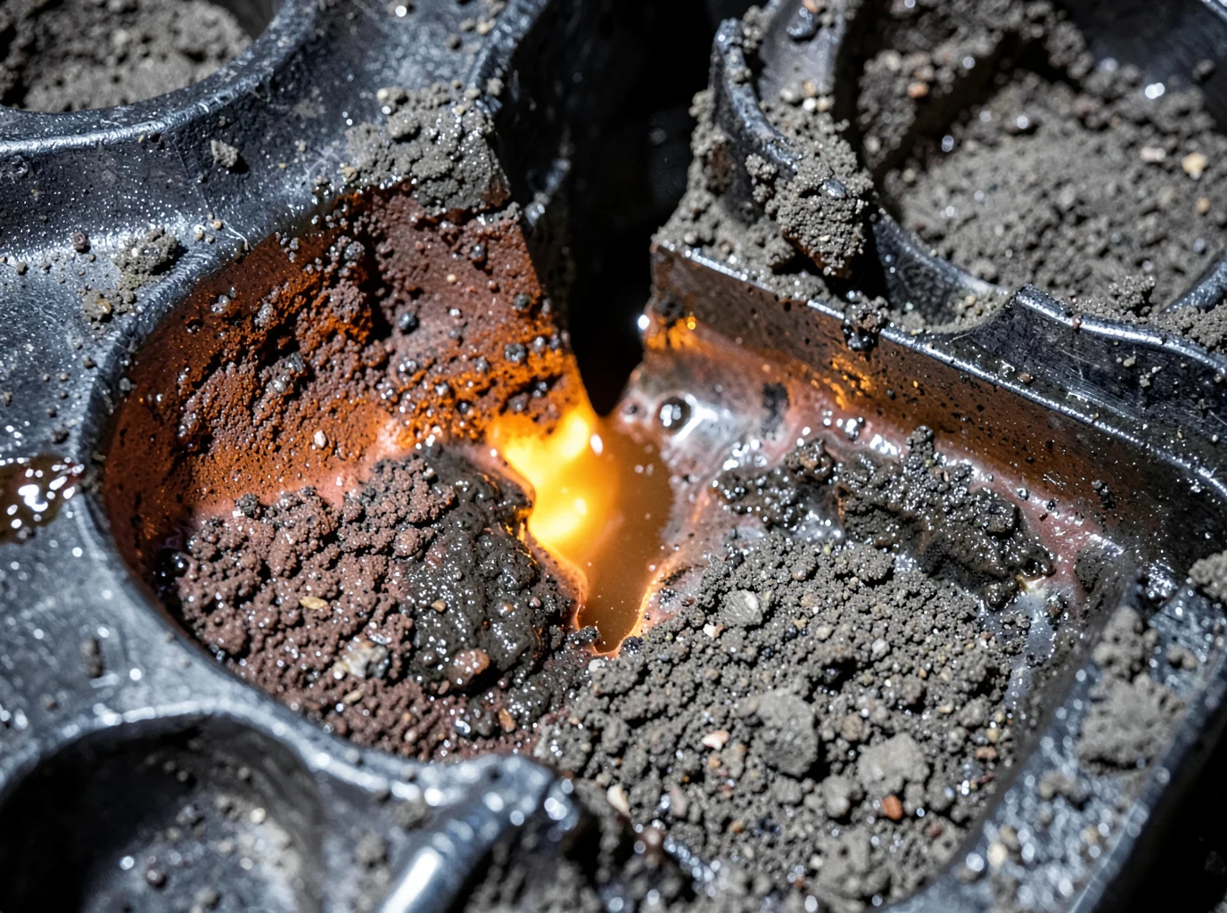
Match the sand to the metal first. Cost, cleanup, and reclamation all follow from that single decision.
Match Sand to Metal Before You Match Sand to Budget
|
Metal Type |
Recommended Sand Combination |
Why It Works |
|---|---|---|
|
Gray iron, ductile iron |
Medium-grain silica sand backing; chromite or zircon facing; high-quality silica full molds for standard parts |
Iron needs moderate permeability, while ductile iron needs extra venting for gas. Silica provides 90–98% SiO₂ at low cost. |
|
Carbon and alloy steel |
Zircon facing + silica backing; chromite/zircon facing for high-temp or complex geometry |
Steel demands high permeability, high refractoriness, and low thermal expansion all at once. |
|
Aluminum, magnesium, copper alloys |
Fine-to-medium silica sand; zircon facing for thin walls; resin-bonded cores for aluminum |
Lower pour temperatures mean you rarely need full refractory sand. Focus on moisture control instead. |
|
Precision, thin-wall, complex castings |
Zircon or chromite facing + reclaimed silica backing |
Fine facing grains improve surface finish while backing sand controls cost. |
Facing sand should run finer than backing sand, but not so fine that mold permeability collapses. Overdoing it trades surface finish for gas porosity risk.
Diagnose Defects by Working Backward from the Sand
|
Defect |
Root Cause |
Fix |
|---|---|---|
|
Pinholes, blowholes |
Excess moisture, low permeability |
Cut water/binder, add vents, coarsen grain |
|
Rough surface, metal penetration |
Oversized grains, weak mold face |
Finer facing sand, zircon/chromite coating |
|
Rat-tails, veining |
Thermal expansion of silica face |
Switch to zircon or chromite facing |
|
Sand inclusions |
Weak surface strength, erosion |
Improve gate design, add erosion-resistant coating |
Practical Build-Outs Worth Copying
-
Steel castings: 10–30 mm zircon facing over silica backing, thickened near gates and hot spots
-
Iron castings: premium silica facing over reclaimed silica backing, chromite/zircon only on critical faces
-
Aluminum castings: fine silica facing over standard silica backing, upgrading only for thin or complex cavities
-
Blended trials: 15–30% zircon aggregate mixed into silica backing cuts veining risk on steel. Verify this through pour trials, not spec sheets alone.
Don’t buy sand by name alone. Request grain distribution, SiO₂/Al₂O₃/Fe₂O₃ content, refractoriness, expansion data, and defect case studies before committing. FoundryMax‘s engineering team builds facing thickness and filtration pairings around your exact alloy and tolerance targets rather than selling sand in isolation.
Conclusion
Your sand selection decides whether parts ship clean or come back with porosity claims. Silica remains the economical workhorse, zircon earns its premium on dimensional accuracy, chromite handles the heat heavy steel throws at it, olivine keeps reactive metals honest, and resin-coated systems unlock geometries green sand casting can’t touch. Matching sand properties like permeability, refractoriness, and grain structure to your specific alloy and tolerance requirements separates scrap-heavy runs from consistent, high-yield production.
Don’t let sand selection stay a guessing game at your foundry. Pull your last six months of defect reports, map them against the sand type in use, and see where the mismatch is costing you. If silica’s limitations or reclamation headaches are eating into margins, it’s time to talk to a materials partner who can audit your process and recommend a switch worth making.