You cut open the casting and find shrinkage porosity sitting right under the riser you sized, placed, and calculated with care. The riser modulus checked out. The feeding distance looked fine on paper. So why did it still fail?
A riser fails when one critical link in the feeding chain breaks, and most foundry teams never pinpoint which one. The six most common failure mechanisms behind riser feeding problems—from premature neck freezing to solidification sequence mismatches—help you diagnose your specific hot spot casting defect instead of guessing. You’ll also get a rapid diagnostic framework to match your defect pattern to its root cause before your next pour repeats the same mistake.
Why Risers Fail: Understanding the Feeding Mechanism
A riser sleeve relies entirely on physics, and physics requires three non-negotiable conditions.
First, the riser has to stay liquid longer than the casting section it feeds. If it freezes first, no amount of extra volume saves the part.
Second, it needs enough usable liquid metal to offset the casting’s solidification contraction, plus whatever metal solidifies inside the riser and neck itself.
Third, a liquid path has to stay open between the riser and the hot spot until shrinkage finishes. Breaking any of these links produces a predictable defect signature rather than bad luck.

The Contraction Problem Nobody Talks About Enough
Metal contraction occurs in three distinct stages. First, the liquid phase cools and shrinks from superheat. Next, the liquid-to-solid transformation drives density-change shrinkage. Finally, the solid metal contracts as it cools toward room temperature. Carbon steel loses around 3% volume during solidification alone. Across common alloys, steel runs 3–6% total shrinkage, aluminum sits at 6–7%, and cast iron requires only 0–3% because graphite expansion offsets part of the loss.
This behavior makes directional control essential during metal casting solidification. Remote sections must freeze first, followed by the hot spot, and the riser last. When that sequence breaks, liquid pressure inside the casting drops, leaving internal cavities, centerline shrinkage, or interdendritic microporosity instead of a sound part.
Reason 1: Riser Freezes Too Early (Thermal Failure)
A riser stops feeding the moment it solidifies before the casting section it protects. Solidification follows the riser modulus, where M = V/A (volume divided by cooling surface area). Under Chvorinov’s rule, solidification time scales with modulus squared (t ∝ M²), so a smaller modulus always freezes faster.
To feed properly, the riser modulus (Mr) must exceed the casting’s hot spot modulus (Mc). Foundry practice targets Mr ≥ 1.2Mc for side risers and 1.1Mc for top risers. At a 1.2 ratio, the riser takes about 44% longer to freeze than the hot spot, which gives you your safety margin. Drop below 1.0, and the riser locks up first.
When this failure happens, the riser looks normal from the outside with no pipe or collapse, even while shrinkage porosity sits buried in the hot spot below. The outer shell solidified intact, but the core kept contracting with no feed path left.
Confirm the defect with X-ray, CT scanning, or ultrasonic testing across the neck and hot spot, backed by centerline sectioning. If Mr/Mc falls below 1.2, enlarge the riser or switch to an insulating riser sleeve or exothermic riser sleeve before touching anything else.
Reason 2: Riser Volume Is Insufficient
Passing the modulus test proves nothing about volume. A riser can freeze late and still starve the casting dry.
A riser’s geometric volume and its usable feeding volume are two different numbers. Only a fraction of that metal flows back into the casting before the neck seals shut. Foundries call this fraction riser volume efficiency (η_v), and it depends on riser shape, whether it is open or blind, and sleeve insulation.
The math foundries skip:
-
Usable volume = η_v × V_r
-
Required feed volume = casting volume × shrinkage rate
Run the numbers on a 1000 cm³ hot spot in steel, 6% shrinkage, standard sand riser (η_v = 14%):
-
Feed required: 60 cm³
-
Riser volume needed: 60 ÷ 0.14 = 429 cm³
Design a 300 cm³ riser instead, and you deliver only 42 cm³ of real feeding capacity. The hot spot still cavitates.
To fix this, switch from sand to an insulating riser sleeve or exothermic riser sleeve. Sleeves push η_v to 40% or higher, letting you shrink riser size by 30–50% while still meeting the volume criterion.
Reason 3: Riser Is Poorly Located (Riser Placement in Casting)
A properly sized riser in the wrong spot still produces shrinkage porosity defects. Placement matters just as much as modulus or volume. The riser must sit right above or beside the casting’s actual hot spot, which is the thickest section and the last area to solidify. If no open liquid channel connects the riser to that hot spot, it cannot feed the area, no matter how much molten metal it holds.
Wall thickness transitions cause this problem constantly. Thin sections freeze first, sealing off the path to thicker regions still in the mushy zone. Put your riser on the thin side, and you cut off your own feeding line. Porosity then shows up at the fillet, the thick wall root, or the junction itself.
Remote bosses, hubs, flanges, and trunnions create their own isolated hot spots because they run thicker than the surrounding wall. A central riser placed too far away lets the boss freeze shut before feed metal ever reaches it. Place risers right next to heavy sections like bosses, and use side risers for thin-walled castings.
Multi-hot-spot castings, such as long plates, frames, or housings with multiple ribs, often need more than one riser. A single riser cannot cover every thick section, and any isolated hot spot left outside the feeding zone becomes a defect site.
Feeding Distance Limits You Can’t Ignore
Feeding distance casting rules set hard boundaries:
-
Edge or corner hot spots: 2T–4.5T from riser to hot spot (T = local wall thickness)
-
Standard steel plate sections without chills: 4.5T–6T maximum
-
Beyond 6T: add a second riser or chill instead of enlarging the existing one
How to Locate Risers Correctly
-
Run a no-riser, no-chill solidification simulation first to find real hot spots.
-
Position risers so solidification flows from thin walls toward thick sections, ending at the riser.
-
Trace the shortest liquid path from each hot spot to its riser—check for necks, sharp corners, or chills blocking it.
-
Verify with thermocouples at hot spots, transitions, and riser necks.
Reason 4: Feeding Distance Is Exceeded
Your riser modulus checks out. Your volume calculation checks out. Yet the casting still cavitates in the middle. Engineers often miss this failure mode because the riser itself is sized properly. The real problem is the distance between the riser and the metal it needs to feed.
Feeding distance is the maximum span over which a riser can keep an open liquid channel inside the casting. Push past that limit, and the metal between the riser and the remote hot spot freezes solid before feed metal arrives. The riser holds plenty of liquid, but that feed metal cannot reach the void.
How to Tell This Apart From Other Riser Failures
The defect signature gives it away. Metal near the riser neck stays dense, confirming the riser fed that zone. Porosity appears far from the riser, often in an isolated pocket between two risers or at the casting’s far end. CT and X-ray scans show the defect running along the section centerline, confirming an unfed island formed outside the reach of every riser.
What Drives Feeding Distance
Several variables shrink or stretch that usable distance:
Alloy type: Aluminum freezes faster and shuts channels sooner than steel, so rules calibrated for steel plate do not transfer.
Mold material: Sand holds heat longer than metal molds or high-conductivity cores, which close the liquid path early.
Pouring temperature: Higher superheat keeps feed channels open longer but risks oxidation and grain coarsening. If pouring temperature is too low, flowability drops fast.
Edge effects: A riser near a free edge gains roughly +2T of extra reach from the added cooling surface.
Fixing an Exceeded Feeding Distance
-
Add a second riser so no isolated hot spot sits beyond coverage. Keep riser spacing under roughly 2× the single-riser effective feeding distance.
-
Place chills between the riser and the remote hot spot to force early freezing there. This pulls the final shrinkage point back toward the riser and can extend effective feeding distance by up to 50%.
-
Add padding by gradually increasing section thickness toward the riser, often starting around 5% per 100 mm. This creates a directional solidification gradient that channels liquid metal back to the riser instead of trapping it.
-
Reposition the riser directly over the actual final-freezing hot spot rather than the geometric center of the casting.
Verify the layout with solidification simulation or centerline CT scanning. Every hot spot must fall inside the coverage zone of at least one riser or chill, with no unfed gaps between them.
Reason 5: Riser Neck Freezes or Is Misdesigned
The neck sits between two forces fighting for its metal. Get its design wrong, and it becomes the weak link nobody checked.
The correct feeding sequence runs casting hot spot first, neck second, riser last. Set the neck modulus near Mn ≈ 1.1Mc to keep it between the casting and your riser (Mr ≥ 1.2Mc). Skip this check, and you leave the middle link in the chain unverified.
Three design variables break necks most often:
-
Cross-section too small: The neck solidifies ahead of time, forming a plug that cuts off liquid feed before shrinkage finishes.
-
Cross-section too large: The neck becomes its own hot spot, causing neck-root porosity and adding riser removal work.
-
Length too long: Extra surface area sheds heat along the feed path, freezing the neck while the riser still holds usable metal.
For rectangular necks, calculate Mn = ab / 2(a+b), where a and b are the cross-section dimensions. Sharp corners and sudden transitions concentrate heat and stress, creating late-freezing zones prone to cracking. Use smooth fillets or tapered, knife-edge transitions instead, but avoid an oversized radius that inflates the modulus.
Fix it: Verify Mc < Mn < Mr directly. Riser volume alone cannot guarantee proper feeding without a verified neck modulus.
Reason 6: Cooling Rate and Solidification Sequence Are Mismatched
Every riser calculation assumes directional solidification moves from thin walls toward the hot spot, then into the riser. Break that assumption, and modulus math stops working. The failure often hides because the riser can be sized and positioned properly, yet still fail when another section freezes out of sequence.
Pouring temperature drives this more than foundries expect. In a compressor support ring case, pouring temperature affected shrinkage porosity more than mold temperature did. Pour too cold, and thin sections or narrow channels solidify early, sealing off the feed path. Pour too hot, and the hot spot shifts away from the planned location toward an ingate, a rib intersection, or an unvented pocket. Pouring too slowly makes it worse by letting the melt cool before the mold fills.
Mold conditions change local heat transfer just as much. Metal tooling and high-conductivity chill zones pull heat quickly, shutting feed channels that need to stay open. Thick sand, closed cores, or insulating coatings do the reverse, creating unexpected hot spots. In one simulation, a thin-wall node reached 50% solidification around 7,000 seconds while the adjacent thick-wall node stayed liquid far longer.
Alloy composition matters too. Wide mushy-zone alloys trap liquid between dendrites, resulting in dispersed microporosity. Narrow mushy-zone alloys form concentrated shrinkage cavities instead. Each defect requires a different fix.
Chills, placed wrong, create their own problem. In a Ductile Iron test case, chills raised the local cooling rate from roughly 0.3 to 1.0. That cut hot spot solidification time by about 45% and pushed the Niyama value past the defect-free threshold. Placed poorly, however, chills choke off the feed entrance before the casting can draw metal.
Fix this by simulating the solidification sequence directly, rather than relying on final freeze times alone. Confirm that the last liquid settles inside the riser rather than at a chill boundary, rib junction, or isolated pocket. Check Niyama values, isolated liquid islands, and local modulus together, then verify the result with sectioning or CT scans on the first casting.
Rapid Diagnostic Guide: Matching Defect Symptoms to Root Causes
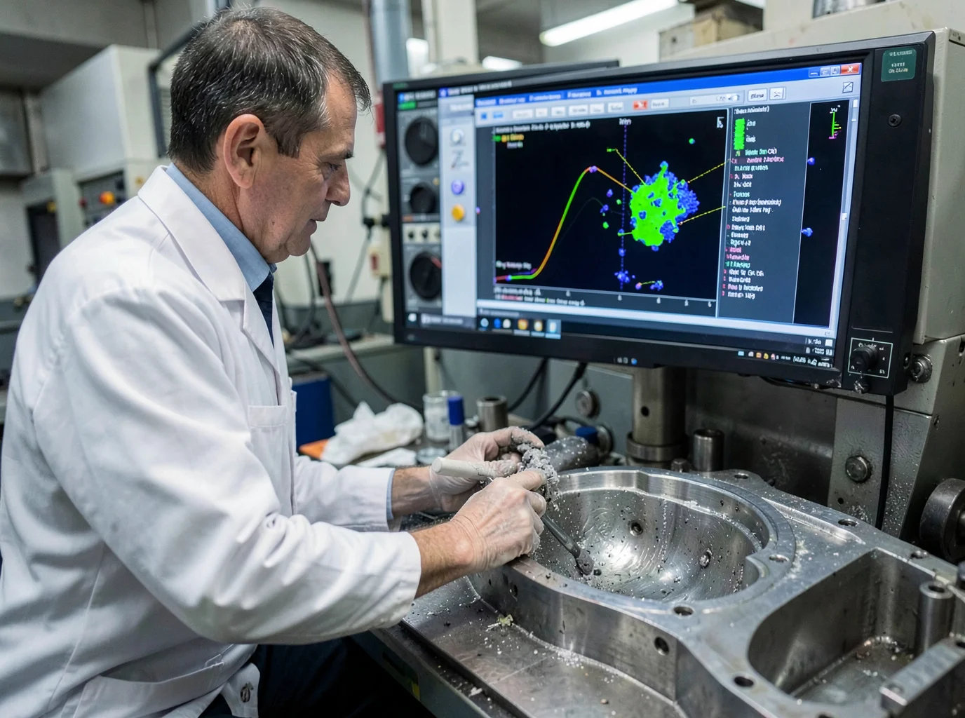
Six mechanisms, one symptom table. Match what you see on the fracture surface to the failure mode before you touch the tooling.
|
Symptom |
Likely Root Cause |
Field Action |
|---|---|---|
|
Riser frozen solid, shrinkage below it |
Thermal failure (Reason 1) |
Section the neck, check Mr/Mc ratio |
|
Deep pipe in riser top, casting still porous |
Insufficient volume (Reason 2) |
Measure pipe depth vs. defect volume, test sleeve upgrade |
|
Riser has pipe but casting porosity persists |
Feeding path blocked |
Section the neck-to-hot-spot path for thin walls or cold shut |
|
Porosity far from riser |
Placement/distance failure |
Run solidification simulation, relocate riser to true hot spot |
|
Porosity at wall transitions, boss roots |
Uncontrolled hot spot |
Measure local modulus, add chills or fillets |
|
Rough, dendritic, irregular cavity |
Shrinkage (not gas porosity) |
Confirm via fracture inspection or radiography |
When Multiple Risers Compete for the Same Hot Spot
Two risers feeding one hot spot create competing feeding paths. Metal flows toward whichever path offers less resistance and higher pressure at that instant. One riser feeds first, stalls, and then the second takes over, shifting defect locations between pours.
Watch for shrinkage alternating between Riser A and Riser B across production runs, defects sitting between risers rather than at the geometric center, or one riser showing a deep pipe while its neighbor stays shallow.
To diagnose it, tag each riser, log pipe depth and defect position across 10+ castings, and overlay the defect locations. If defects swing between risers, block one temporarily and watch where the defect moves.
Riser Design Verification Checklist (Prevention Framework)
Six failure modes, one gate before tooling approval. Skip the gate, and you’re back to guessing which mechanism broke.
Run these six checks in sequence:
-
Map every hot spot. Chart wall thickness, hot junctions, and isolated thick sections. Calculate Mc = Vc/Ac for each candidate. Evaluate any thickness ratio over 2:1 on its own.
-
Verify the modulus chain. Confirm Mr ≥ 1.2Mc for side risers and Mr ≥ 1.1Mc for top risers. Set the neck modulus 10% above Mc.
-
Check volume against shrinkage. Required riser volume = shrinkage volume × safety factor. Start with 1.5–2.0, then dial it in with simulation and first-article results.
-
Confirm feeding distance coverage. Use 10×Mn as an initial estimate, or 4.5t for steel plate sections, then verify it against real process data.
-
Verify neck connectivity. The neck must stay liquid until feeding finishes, with no early-freezing thin sections or chills cutting it off.
-
Simulate and inspect. Run solidification prediction, then check the first casting with X-ray, CT, or sectioning. Never release on appearance alone.
Build a tracking sheet with three tabs: hot spot inputs, riser calculations, and coverage/release status. Flag red for failed checks, yellow for pending simulation, and green for signed-off verification. Feed defect locations back into this sheet after every production run so your parameter library gets smarter with each casting instead of repeating the same six mistakes.
Conclusion
Riser failure is rarely a mystery once you know where to look. Most failures trace back to three root causes. The riser froze before the casting did, it lacked enough feed metal, or the feeding path broke the thermal connection too soon due to neck size, distance, or geometry. Shrinkage porosity signals that something in the riser modulus calculation or placement strategy needs correcting.
Catch these issues before they reach the pour floor. Run your next design through the verification checklist in this guide. Cross-check riser sizing against actual feeding distance requirements instead of rules of thumb. If you still see inconsistent results, validate your assumptions with solidification simulation rather than another round of trial-and-error castings.