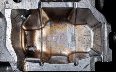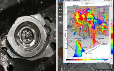
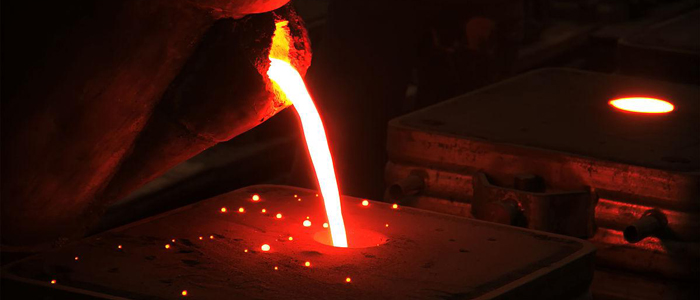
A batch of castings fails inspection. The surface looks clean, but X-ray or machining reveals dark, irregular patches buried beneath. These slag inclusions cost you yield, rework hours, and a difficult conversation with your customer. If you are reviewing a defect report to determine whether the problem started in the furnace, the ladle, or the gating system, slag entrapment remains one of the most common and misunderstood defects in steel foundries.
This guide breaks down where non-metallic inclusions in steel originate, tracing the path from melt chemistry and ladle transfer through pouring basin design and mold interaction. You will also find the diagnostic checklist and control measures foundries use to catch slag before it reaches the mold, so you can stop firefighting the same defect every production cycle.
What Are Slag Inclusions In Steel Castings (And Why They Matter)
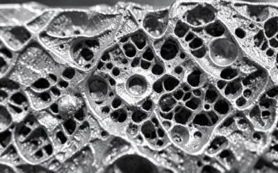
A slag inclusion is nonmetallic material trapped inside solidified steel. It enters the mold with contaminated molten metal or forms during the pour through oxidation reactions with slag, refractories, or mold material. The chemistry varies: oxides of iron, silicon, manganese, and aluminum; silicates; refractory fragments from the furnace, ladle, or tundish; and flux or dross residue. Because these contaminants are lighter than liquid steel, they float upward and collect near cope surfaces, upper casting zones, and turbulent fill regions. They show up as irregular dark pockets, glassy ribbons, or translucent white-to-green films, with some reported deposits spanning 2–3 inches across.
Why this casting defect type matters:
-
Fatigue failure: Inclusion clusters near the surface act as crack-initiation points. In castings with discontinuities, fatigue strength can drop to roughly one-quarter of tensile strength.
-
Mechanical loss: Reduced ductility, fracture toughness, and corrosion resistance.
-
Machining breakout: Near-surface inclusions rupture during turning or grinding, causing pits and tool damage.
-
Leak risk: Inclusions intersecting pressure boundaries create through-paths in valves, pumps, and hydraulic components.
-
Rejection cost: Inclusion-related defects have driven 30–40% rejection rates in some sand-mold applications.
Root Cause #1: Oxidation And Contamination During Melting And Charging
The defect often starts before metal ever reaches the mold. Oxidation inside the furnace and ladle sets up everything that follows.
Why Aluminum, Silicon, And Manganese Create Oxide Inclusions
Aluminum bonds aggressively with oxygen. After deoxidation, it forms high-melting-point Al₂O₃ particles that rise slowly and get trapped by the moving melt instead of floating clear. Inclusions in molten steel can measure as small as 0.05 mm, which is too fine to escape without argon stirring, electromagnetic stirring, or particle coalescence.
Silicon yields SiO₂, and manganese forms MnO. When Si and Mn deoxidize together, they often form solid silica combined with liquid manganese silicates. Higher dissolved oxygen creates more of these silicate inclusions at larger sizes. Chromium forms Cr₂O₃, but it deoxidizes more weakly than Al, Si, or Mn, so operators rarely use it on its own. Instead, it pairs with other oxides into stubborn spinels that resist removal.
Oxygen enters the bath through air contact, moisture in damp charge materials that splits into hydrogen and oxygen, rust reduction, and oxide transfer from slag or refractories.
Dirty, Rusted, Or Misclassified Scrap Raises The Risk
Rusted scrap carries Fe₂O₃, Fe₃O₄, and FeO. Once it hits hot metal, aluminum, silicon, and manganese reduce those oxides, generating new inclusions and triggering localized gas reactions. High oxygen levels also raise the odds of CO formation and porosity.
Oily, sandy, or coated scrap causes worse problems. Organic residue pyrolyzes into gas and carbon buildup, while sand, refractory fragments, and coating ash directly seed inclusion nuclei. Wet scrap can cause violent boiling, spatter, and slag re-entrainment.
Sorting errors compound the issue. Charging heavily oxidized scrap, slag chunks, refractory debris, or mismatched alloys spikes total oxide content and destabilizes melt chemistry, throwing off deoxidizer dosing. Adding aluminum-bearing scrap to a high-oxygen bath rapidly produces large volumes of Al₂O₃.
Practical fix: Grade incoming charge into four tiers: clean dry metal, lightly oxidized material, rusted or coated scrap, and slag or refractory residue. Isolate or pre-treat the last two categories. Inspect every batch for moisture, rust, oil, sand, scale, and material ID before it goes into the furnace.
Slag, Flux, And Refractory Erosion Add More Contaminants
Incomplete slag skimming, turbulent tapping, or surface churning during pouring all pull oxidized slag back into the melt. Unreacted or overdosed flux forms high-melting-point particles and viscous films that travel straight into the mold.
Refractory wear adds a third layer of contamination. Furnace linings, crucibles, stopper rods, and ladle materials erode under thermal and mechanical stress, shedding Al-Si oxides, MgO, or spinel particles into the bath. Eroded refractory also alters slag viscosity, making it harder for inclusions to float out and separate.
Control priorities: Keep linings dry and intact, reduce free-fall height and pour turbulence, leave the bath surface undisturbed after skimming, and maintain steady, continuous ladle transfers to prevent air entrainment and slag pickup.
Deoxidation Practice In Steelmaking: Where The Chain Reaction Starts
Dissolved oxygen at tap typically runs 400–800 ppm. Incomplete deoxidation leaves residual oxygen to react with carbon during solidification, causing boil, porosity, and fresh oxide inclusions.
A standard sequence runs from Si-Mn pre-deoxidation to ladle diffusion deoxidation, ending with vacuum degassing. Sound practice brings total oxygen down from roughly 100 ppm to about 10 ppm, with cleaner grades reaching below 5 ppm.
Where the process breaks down:
-
Deoxidizers added too early: Slag and air consume Al, Si, and Mn before they can do their job, leaving high residual oxygen. Later alloy additions then re-oxidize and generate secondary inclusions.
-
Insufficient quantity or poor mixing: Oxygen never binds completely, allowing CO to form during solidification while fine oxides accumulate without rising.
-
Excess or localized aluminum addition: This generates coarse Al₂O₃ clusters or calcium-aluminate inclusions quickly, even as total oxygen drops. These larger particles harm fatigue life far more than fine ones do.
-
Unbalanced Si-Mn ratio: This generates solid SiO₂ or sticky manganese silicates. In one documented trial, total oxygen stayed near 35 ppm under Si-Mn deoxidation, but higher initial oxygen still produced larger, denser inclusions.
-
Stirring mismatch: Insufficient stirring prevents deoxidation products from coalescing to float out, while excessive stirring pulls surface slag and air back into the melt.
Reliable deoxidation comes down to sequencing. Addition order, injection point, stirring intensity, holding time, and skimming must work together instead of being managed in isolation.
Root Cause #2: Slag Entrapment During Ladle Transfer and Pouring (Ladle Slag Carryover)
Even a clean furnace tap turns dirty the moment steel hits the ladle. Slag entrapment in casting usually happens during this transfer stage.
Tapping Mechanics: When Slag Rides The Stream
Tapping has three danger zones. Tilting early pulls furnace slag toward the tap hole. Mid-pour, a falling bath level creates vortices that draw slag into the stream. Late draining carries the highest risk, because the thinning heel forms a drain funnel that pulls residual slag straight into the ladle. Never chase a complete drain. Shut the slide gate or drop in slag-stopping darts or balls the instant you see dark bands in the stream, a rising droplet ratio, or the slag-metal interface nearing the tap hole. Infrared or electromagnetic slag detection can cut carryover by up to 90%. Using a stopper ball alone brings carryover down to 3 kg/ton steel.
Ladle Preheat And Refractory Condition
Cold ladle linings chill the bath on contact, spalling frozen metal and oxides into the melt. Typical preheat targets run 980–1090°C for steel ladles and 800–1200°C for general refractory. Never fill a ladle that has not reached operating temperature or still shows moisture, loose brick, or cracking, especially around the impact pad, slag line, and gate brick.
Air Exposure And Turbulent Transfer
Open streams, unsealed long nozzles, and exposed bath surfaces trigger secondary oxidation, generating alumina and spinel inclusions. Turbulent transfer compounds the problem when high-velocity flow shears the slag layer at the meniscus and drags slag into the mold. Keep long nozzles submerged and argon-sealed, maintain a steady stream, and back off the pour speed the moment a vortex or slag film appears instead of holding the rated rate.
Root Cause #3: Non-Metallic Inclusions Introduced by the Mold and Core System

The mold itself can be the source of contamination. Fast-moving metal strips sand, coatings, and refractory aggregate off the cavity wall, trapping those fragments inside the casting.
Sand Washout And Core Breakdown
High pour velocities, steep drops, turbulent gate corners, or a stream striking the mold wall will wash away sand grains, coating layers, and refractory aggregate. These loose fragments mix with oxide films and slag to form sand-related inclusions.
Cores fail in much the same way. Low core strength, incomplete baking or curing, uneven binder distribution, or thermal shock during the pour causes core sand to crumble into the melt. Underbaked oil-sand cores also reabsorb moisture, leading to core erosion, gas porosity, and inclusions at the same time.
Shell And Coating Failures
Shells shed flake or granular inclusions during the pour if they crack, delaminate, dry incompletely, or suffer from localized weak spots and poor coating adhesion. Shell quality standards reject these conditions outright. Surface coatings detach under flowing metal if they are applied too thick, left damp, powdering at the surface, or thermally mismatched to the core.
The highest risk comes from combining high pour temperatures, violent turbulence, weak cores or shells, low permeability, and excess moisture, which together generate sand, oxide, and gas defects at once.
Root Cause #4: Turbulence-Induced Slag Entrapment Caused by Gating System Design Flaws
Metal velocity decides whether a pour stays clean or turns into a slag factory. Every splash, impact, or fold at the liquid surface creates a bifilm—two layers of oxide skin folded together with air trapped between them. That bifilm does not dissolve. It rides the flow straight into the casting, creating a crack initiation site, a non-metallic inclusion, or a hot tear nucleus.
Why Turbulence Creates Oxide Double-Films
Sharp turns, sudden section changes, and free-fall drops cause local jetting, backflow, and surface breakup. Fast metal folds oxide skins, erodes sand molds, and drags refractory fragments straight into the stream.
Keep velocity at the gate or casting base below 0.8 m/s. In high-risk sections, target a cavity gate speed of 0.5–1.0 m/s to cap simulated air entrainment at 15%. For steel castings, maintain a Reynolds number below 20,000 to prevent severe turbulence. Filters dampen flow disturbances, but they cannot compensate for poor gating geometry.
Common Gating Design Flaws That Trigger Entrapment
Excessive metallostatic head or undersized gate area: Spikes velocity at a fixed pour rate, causing impinging jets and surface rollover.
Top pouring: Free-fall drop height forces the first metal into the cavity to drag in slag, oxide films, and air before the gate stabilizes.
Right-angle turns and abrupt section changes: Trigger flow separation, vortices, and localized high-speed zones. Fillets and gradual transitions prevent this.
No gate well or buffer pocket: Fails to absorb impact energy, letting high-velocity metal shoot straight into the runner or cavity.
Uneven gate distribution: Starves some gates while overloading others, driving up local speed and entraining films at the active openings.
Filters Don’t Fix A Bad Design
Ceramic foam Filters do not catch every bifilm. Severe turbulence shreds oxide films into pieces small and dense enough to slip through the filter mesh. One documented failure combined a vertical filter, a top gate, and partial bottom gates, a layout that amplified turbulence instead of controlling it. Correcting this required horizontal filtration, an extended runner, a slag trap at the runner end, and a switch to full bottom filling. In that same case, replacing two 25 mm tube gates plus a top gate with four 25 mm bottom tube gates increased total gate area, lowered per-gate velocity and Reynolds number, and eliminated secondary inclusions.
Runners also need a sacrificial extension past the first branch point. Without it, the dirtiest initial metal enters the cavity instead of settling out harmlessly.
Gating Design Checklist For Slag Trap Gating Systems
-
Gate velocity target: <0.8 m/s, checked against 0.5–1.0 m/s at high-risk sections
-
Flow regime: Reynolds number <20,000 where achievable
-
Geometry: no sharp turns, no sudden expansions, fillets on every transition
-
Fill strategy: bottom or rising fill over top-gated designs
-
Slag control features: gate wells, runner extensions, end traps, vortex catchers, or overflow pockets
-
Filter validation: check pressure drop, fill state, capture efficiency, and bypass risk before relying on it
How To Diagnose And Locate Slag Inclusions In Steel Castings
A rejected casting tells you very little on its own. The surface can look clean while non-metallic inclusions hide a few millimeters below. Diagnosing them requires working from the outside in, then matching the defect to where it formed in the mold.
Match The Test Method To What You Need To Find
No single inspection method catches everything. Each technique answers a different question:
Visual inspection (VT): Cheap, fast, and conducted before and after cleaning or machining. VT flags surface black spots, pits, sand entrapment, and slag pockets near gates, riser roots, and parting lines. It cannot confirm inclusion chemistry or detect defects below the surface.
Radiographic testing (RT): The primary tool for internal non-metallic inclusions, slag pockets, sand entrapment, shrinkage, and gas porosity in thick-walled or complex steel castings. RT provides a 2D projection (count, rough position, and severity grade), but it loses sensitivity on thin, film-like inclusions lying parallel to the radiation beam, and it cannot identify the material composition. Steel castings are graded against ASTM E446 (≤51 mm), E186 (51–114 mm), or E280 (114–305 mm) reference radiographs.
Magnetic particle testing (MT): Effective for surface and near-surface slag, cracks, and folds on ferromagnetic castings, particularly after machining or local grinding. MT misses deeper internal defects and requires a clean, magnetizable surface with proper field direction.
Liquid penetrant testing (PT): Best for surface-breaking slag pockets, sand porosity, and fine connected cracks on complex geometries. It cannot detect closed internal inclusions, and oil, coatings, or rough cast surfaces cause false indications.
Metallography: Using samples taken from areas flagged by RT, ultrasonic testing, or machining, metallography confirms inclusion morphology, distribution, and interfacial oxide films. It quantifies area fraction, size, and spacing. Because it is destructive, prior non-destructive testing must guide where you section the part.
SEM/EDS: The source-tracing method. High-magnification imaging combined with elemental analysis on a polished specimen or fracture surface distinguishes furnace slag, refractory, sand, and deoxidation products by their Al, Si, Ca, Mg, Mn, and Fe signatures. Because it is semi-quantitative and evaluates a microscopic area, it supplements bulk inspection rather than replacing it.
A Practical Diagnostic Sequence
Post-cleaning VT: Record defect coordinates, surface orientation, and distances from gates, risers, and parting lines.
RT on full volume or targeted zones: Select reference radiographs based on wall thickness per ASTM E446, E186, or E280. Follow ASTM E1030/E1030M for inspection procedures, using E94 and E142 for image quality control.
MT or PT recheck: Prioritize areas flagged by radiography, along with gate stubs, grind areas, and machined surfaces.
Targeted sampling: Section the casting along the defect’s longest axis to preserve the interface between the inclusion and the steel matrix. Record the cut coordinates and depth.
Metallography, followed by SEM/EDS: Evaluate morphology and distribution under low magnification first, then run elemental spectra to identify source chemistry.
Compare against process materials: Match the inclusion against slag, refractory, and molding sand samples to tie the defect to a specific process step.
Let Defect Location Point You To The Cause
Where the inclusion settles provides direct diagnostic evidence. Most foundry investigations start with defect position:
Near the ingate, sprue, or runner entrance: Dense, coarse inclusions, often showing erosion marks. These point to early-pour slag, refractory carryover, excessive gate velocity, or a failed filter. Check the initial melt sample and inspect the filter seat.
Early fill zone, away from the far end: Thin, film-like inclusions. These indicate that the initial oxide skin folded into the metal stream during an unstable or interrupted pour.
Last-to-fill zones, far end, cavity top: Slag clustered with porosity or cold shuts, floating and accumulating where venting is poor. Check overflow wells, risers, and slag traps for capture failure.
Top surfaces near risers: Low-density inclusions carried along by riser feed flow, pointing to incomplete ladle skimming.
Parting lines, core prints, core surfaces: Irregular, sand-like inclusions caused by mold washout, core breakdown, or coating failure. SEM/EDS detection of Si, Al, or Zr confirms a mold-system source rather than melt chemistry.
Same location across multiple castings: Indicates a gating design flaw rather than an isolated operational slip. Side- or top-gated molds produce 2.5–5 times higher air entrainment than bottom-gated designs, which explains repeat defects oriented along the same runner line.
Random fine inclusions scattered through the cavity: Caused by turbulence, high pour speeds, or an unchoked runner drawing air. Metal turbulence causes an estimated 80% of casting defects, so this distribution points to gating hydraulics rather than furnace practice.
Document Everything The Same Way Every Time
Inconsistent records allow recurring defects to linger for years. At minimum, log: casting ID, heat number, test method, equipment and energy level, wall thickness, image quality indicators, defect coordinates, length or area, assigned severity grade, re-inspection results, macro photos, and final disposition. SFSA inspection guidelines and ASME BPVC Section V, Article 2 serve as standard references for RT acceptance criteria, though the purchase order governs the applicable code edition. Systematic records ensure that a single root-cause analysis permanently updates foundry practice.
Slag Prevention Strategies in Melt Control (Melt Control Best Practices)
Melt control makes or breaks slag prevention. Every choice you make before metal hits the ladle determines how much cleanup work falls on the Gating System later.
Charging Standards That Cut Oxide Load Before Melting Starts
Charge materials—returns, ingots, and alloys—need verified chemistry, clean surfaces, and minimal oxidation. Sand on gates and risers, rust on scrap, oil, and damp coatings all generate slag the moment they enter the bath. If you melt steel, strip or minimize FeO/Fe₂O₃ scale before charging. For aluminum, eliminate oil, cutting fluid, and moisture. Every ladle, skimming tool, charging bucket, and filter must be bone dry before it touches molten metal, because wet tools cause violent spattering and localized oxidation. Isolate returns by batch and inspect them. If scrap is rusty, wet, oily, or caked in sand, clean it, dry it, or downgrade it instead of throwing it straight into the furnace.
Operating Practices That Limit Oxidation During Melting
Clear oxide scale, sand, and debris before charging. Stick to a melt-fast, hold-short routine. Cut back on bath stirring, avoid drop-charging from high above the bath, and let the surface cover rest undisturbed once it stabilizes. When you skim, work only the top layer without digging deep or churning oxides back into the melt. Finish alloying in the furnace whenever you can rather than in the ladle, and keep ladle hold times short. In steel operations, skim twice: once right after initial superheat, and again before tapping. Typical superheat runs 150–200°C above liquidus, adjusted for your grade and equipment.
Flux Timing And Function
Flux lowers the slag melting point, gathers suspended oxides so they float to the surface, and prevents buildup on furnace walls and induction linings. Add flux after the charge has melted down and visible oxide slag forms. Never use flux as a shortcut to fix dirty charge material. Pick your flux chemistry and dosage based on alloy system, furnace design, and supplier recommendations. Overdosing eats refractory linings, kicks up heavy fumes, and burns off good metal. On steel, keep cover slag uniform across the entire surface, since bare spots or mismatched chemistries pull inclusions back into the pour stream.
Recommended Skimming Sequence
-
Hold the bath at target temperature and chemistry long enough for oxides to float to the top, setting the exact time from inclusion checks.
-
Push surface slag toward the tap or ladle spout gently instead of forcing it down into the liquid.
-
Work shallow passes across distinct zones using preheated, dry tools. Avoid deep digging and repetitive sweeping.
-
Complete the final skim before tap or transfer, and shut off slag flow during the final drain by tilting the furnace.
-
Position mechanical skimmers before filling the ladle, then clear away any remaining slag once filled.
-
Pour promptly after skimming to prevent re-oxidation, doing one quick surface inspection before release.
-
In continuous casting tundishes, install weirs, dams, turbulence inhibitors, and active cover flux to stop slag carryover. One documented plant study lifted inclusion removal from ~30% to over 43% after optimizing these flow controls.
Furnace And Ladle Inspection Priorities
Inspect the furnace walls, hearth, door, taphole, ramp, sill, and metal line after every cleanout or skim. Ramps and sills take direct hits from charging scrap and skimming rakes, so inspect them for structural wear. Watch the belly band at the slag line especially close. That band takes constant punishment from oxides, flux, and heat cycling, making it the first area to give out. If you spot spalling, cracks, bulges, leaks, strange buildup, thin spots, or discolored refractory, shut the unit down for repairs immediately. Never try to nurse damaged lining with extra flux or longer preheats.
Before bringing a ladle into service, inspect the lining for cracks, wash-out, bottom pitting, pour-lip damage, and slide-gate or stopper condition. Always confirm the refractory is thoroughly preheated and dry. Check the bottom impact pad and slag line after every heat. Log ladle life against tonnage, alloy grade, bath temperature, and cycle count. Pull the ladle from service whenever it reaches the wear limit or shows a through-crack, because slag carryover ruins tundish linings just as fast downstream.
Tundish maintenance calls for pre-pour checks on the working lining, dams, weirs, impact pads, and slag line, followed by thorough cleanouts and erosion tracking after each sequence. Keep the tundish powder layer uniform. Exposed metal and entrained slag create macro-inclusions above ~200 μm in the finished cast. Log every heat, steel grade, pouring temperature, refractory lot, deepest erosion point, spall pattern, and reason for lining tear-out. These maintenance logs turn deoxidation practices and melt control into measurable shop-floor standards instead of guesswork.
Control Measures During Transfer and Pouring
A clean tap means nothing if the ladle spout, slide gate, or stopper rod still carries frozen slag from the last heat. Before transfer begins, run a four-point visual check across the ladle lip, nozzle, trough, and Pouring Basin. If you notice smoke, discoloration, flow surges, or spatter during the pour, stop immediately.
Keep Every Surface Dry And Preheated
Ladles, troughs, tundishes, and pouring basins must be bone-dry and thoroughly preheated. Wet refractory flashes to steam on contact and causes violent spatter. Never make exceptions for refractories that cooled down for “just a few minutes.”
Shroud Discipline And Pour Curve
Submerged shrouds need coaxial alignment, zero cracks, and a verified seal after installation, since any air suction ruins the protection. Follow that with a pour curve built on a low-flow start, smooth ramp-up, steady fill, and reduced end-rate. Base your flow adjustments on meniscus behavior, spatter, and stream color instead of relying on ladle tilt angle alone.
Detection And Heel Retention
Electromagnetic slag sensors can detect layers as thin as 10–15 mm and trigger automatic flow reduction. Without sensors, keep a steel heel in the ladle. Draining the vessel completely pulls in late-stage slag, while leaving a heel stops most carryover.
Gating System Optimization Design Plan
Gate geometry and filter selection work together. Neither one fixes mistakes made by the other.
Bottom-Pouring Vs. Side-Pouring: Pick Based On Casting Geometry
|
Factor |
Bottom-Pouring |
Side-Pouring |
|---|---|---|
|
Fill pattern |
Metal enters low, liquid rises steadily |
Metal enters horizontally or at an angle |
|
Best fit |
Tall, thin-wall, oxidation-sensitive castings that need bottom-up filling |
Small-to-mid size parts with simple shapes and short fill distances |
|
Strength |
Low impact, less gas and oxide-film entrainment; suited to pressure-sealing parts |
Shorter gating, simpler tooling, higher yield, and easier multi-gate layouts |
|
Risk |
Longer runners, higher heat loss, and cold shuts near the bottom |
Side jets wash mold walls and cores, pushing inclusions straight into the cavity |
|
Fix |
Add filters, top risers, or staged bottom entries; control inlet velocity |
Angle ingates upward or tangentially, avoid direct core hits, and add a slag trap at the runner end |
Route runners below the cavity and position ingates on the top or upper-side wall. Low-density oxides will stay trapped in the runner rather than washing into the part.
Three Slag-Catching Features That Earn Their Place In Every Gating System
Runner extension: Run the channel past the final ingate to catch cold metal, oxide scale, and loose sand. Match or exceed the cross-section of the main runner, and finish with a rounded dead-end pocket to stop secondary swirls. Start with 1–2 hydraulic diameters past the last gate, then verify the results with fill simulation and section cuts.
Dross/slag well: A recessed pocket below the runner floor that catches dense metal while lighter oxides, slag, and bubbles stay behind. Make it deeper than the runner channel, with rounded entries and no sharp corners. Feed ingates from the upper or side-upper zone, never from the floor where sediment settles.
Vortex trap: Metal feeds tangentially into a rounded chamber, spinning inclusions out toward the wall while clean metal drains through the quiet center. Avoid sharp expansions or right-angle turns. This works well for aluminum and magnesium alloys that form heavy oxide skins, and it integrates cleanly into side-gated or multi-ingate systems. A deep pouring basin with a dam or stepped floor will hold back the dirtiest first metal before it ever enters the downsprue.
Filter Design For Molten Metal: Matching PPI To The Job
PPI sets the trade-off. Lower PPI gives you larger pores, less flow resistance, and higher throughput. Higher PPI catches finer inclusions, but it chokes faster and requires more static head to stay open.
|
Filter |
Pore Size |
Best Use |
Recommended Alloys |
|---|---|---|---|
|
10 PPI |
~2.5–3.0 mm |
High-flow, thick-wall, large castings; coarse slag only |
Large aluminum, magnesium, and copper castings; dirty charge |
|
20 PPI |
~1.2–1.5 mm |
General foundry work; balances flow rate with cleanliness |
Standard aluminum, gravity casting, common automotive parts |
|
25 PPI |
~0.9–1.1 mm |
Mid-to-high cleanliness for structural parts |
Aluminum structural components, thinner-wall castings |
|
30 PPI |
~0.7–0.9 mm |
High cleanliness for pressure-tight and safety components |
Premium aluminum, ductile iron, copper alloys |
|
40–60 PPI |
Finer pore |
Thin-wall, aerospace, critical clean pours |
Aerospace aluminum, thin sections; unsuitable for dirty melt |
Quick selection rules:
-
Large or thick-wall parts with high flow rates: 10–20 PPI
-
Standard aluminum gravity casting: 20–30 PPI
-
Structural or pressure-sealing parts: 30–40 PPI
-
Thin-wall, high-integrity castings: 40–50 PPI, but increase the filter surface area and re-check fill times
-
Magnesium alloys: consider MgO-based filters; large castings take 10–20 PPI, while standard magnesium pours take 30–40 PPI

Size the total filter area around flow rate, pour duration, melt temperature, and allowable pressure drop. As a working rule, pick the largest pore size that satisfies your cleanliness target, then verify it with a trial pour. A 30 PPI filter only works if the melt is already reasonably clean, the filter face is large enough, and you have sufficient head pressure to push metal through the mesh.
A Reference Layout That Ties It All Together
Pouring Basin
│
▼
Sprue (kept full, no air gap)
│
▼
Sprue-base buffer well
│
├──────────── Runner ────────┬── Ingate → Cavity
│ ├── Ingate → Cavity
│ └── Filter → Ingate
▼
Runner extension / Dross well
(traps cold metal, oxide scale, sand)
Operational checklist:
-
Put a buffer well at the sprue base so metal does not slam directly into the runner floor.
-
Taper the runner down or size it to maintain constant velocity, avoiding pressure drops that pull in air.
-
Cut ingates from the upper or side-upper runner wall rather than the bottom where sediment gathers.
-
Run the runner past the last ingate to serve as a terminal slag trap.
-
Seat filters near the end of the runner, right ahead of the ingates, or within a tight pocket that prevents molten bypass.
-
Round every transition through runners, slag pockets, and filter housings to cut turbulence, air intake, and folded oxide films.
Mold & Core Quality Assurance

A pre-pour checklist catches most slag entrapment before metal ever moves. Checking the coating, hardware, and cavity addresses each failure point before it causes scrap.
Coating Penetration And Drying Standards
Keep coating penetration to 1.0–1.5 mm on standard sand molds and 2–3 mm on cold-box or high-gas cores. Penetrating deeper kills permeability and triggers porosity defects. Once dried, coatings must show full coverage on parting lines, sharp corners, and core prints, with no cracks, pinholes, blistering, delamination, or bare spots. Target a 0.5 mm working thickness for water-based coatings, and verify it with a wet-film gauge or weigh-check instead of eyeballing the wash. Air drying takes 1.5–3.0 hours, while forced air at 80°C ±5°C cuts that to 4–8 minutes. Cap drying on alkaline phenolic-bonded core coatings at 150°C so the resin does not break down. A touch, wipe, or hardness-pen test should show zero powdering and no cold or damp patches.
Venting, Permeability, And Hardware Condition
Place vents at cavity high points, blind pockets, and core-print ends. Never let coating or mold paste plug them. Chills, inserts, and chaplets must be clean, dry, and free of rust or oil—preheat cold chills before loading them into the mold. Check core strength, cavity dimensions, mold match, and dryness before sign-off. Any crack, dimensional deviation, or blocked vent requires rework before pouring.
Slag Inclusion Defect Troubleshooting Guide (Troubleshooting Guide By Defect Location)
Print this table and keep it on the shop floor. It turns vague inspection reports into concrete corrective action.
|
Defect Location |
Suspect First |
Verify |
Fix |
|---|---|---|---|
|
Ingate / gate root |
Gate erosion, turbulent fill, failed filter |
Gate cross-section, impact marks, filter seat |
Widen the gate well, reposition filter, cut pour height |
|
First-fill zone |
Dirty ladle heel, unstable first stream |
Ladle bottom sludge, skim completeness |
Add a runoff trap, stabilize the stream before gate entry |
|
Last-fill zone, far end |
Slow-moving metal, poor venting |
Vent and riser position, pour temperature |
Add an overflow well, check for blocked vents |
|
Top surface, core underside |
Low-density inclusion flotation |
Core gap, casting orientation |
Add top venting, reorient the casting |
|
Random internal, found after machining |
Overall melt cleanliness, air pickup |
Heat log vs. casting map, SEM/EDS |
Reduce transfer exposure, retrain on skimming |
|
Corners, blind pockets |
Stagnant flow, trapped dross |
Fillet radius, coating adhesion |
Add a local vent, redirect fill path |
|
Recurs after process change |
Temperature, filter, gating, or treatment change |
Before/after process log |
Change one variable at a time, track 3+ heats |
Conclusion
Slag inclusions in steel castings rarely come from a single mistake. Most often, they are the final symptom of small oxidation events that compound across melting, transfer, and pouring. Stopping them requires tighter deoxidation control at the furnace, cleaner ladle transfers, and a slag trap gating system engineered to slow turbulence before metal ever reaches the mold cavity. Get those three right, and non-metallic inclusions in steel castings drop sharply, along with your scrap rate.
If you are seeing recurring inclusion defects, map the defect location back to its process stage using the troubleshooting framework above rather than patching the gating system and hoping. If you would rather skip the trial-and-error, FoundryMax‘s metallurgical team has already solved this problem across hundreds of production runs. Reach out, share your casting drawings, and let’s engineer slag out of your next pour.